About Comments

Comments are enabled on all postings. Click a posting to find the comment box. Comments are moderated and appear after my review.
Showing posts with label Project20. Show all posts

Sunday, 4 June 2023

Corona Quay Video

Threw this little video together using the default Windows 10 Video Editor. 

Corona Quay was created in the first year of the Covid-19 pandemic. Here we see a Class 33 and Terrier shunting wagons on the quay to deliver a chlorine tanker to the paper mill and an open wagon to the transshipment shed. Class 33 and rolling stock are scratch built using 3D printing. Terrier is the Dapol offering. Vic 24 Clyde Puffer is a Scalescenes 00 card kit blown up to 0 gauge. Buildings are mostly scratch built in corrugated cardboard.

Whilst much enjoyment was gained from building the layout it is rarely run because it can only be fully set up in the garden, due to indoor space limitations. Hence summer running on fine days only.

Layout construction detail appear under Project 20 on the right.

Saturday, 4 June 2022

A Driver for IXO BR FORD THAMES ET6

This story is a follow on from my February 2021 posting about a lorry for Corona Quay (please read that first). Previously I wanted to correct the driving position and fit a driver but could not fathom how to take the cab off to gain access.

It is strange sometimes how events manifest. Nearly 14 months later I was just sitting and playing my guitar and looked up to the windowsill where the lorry on display caught my eye. On a whim I decided to have another look to see if I could do the upgrade.

I like the model but it irks me to see that the foreign manufacturer made this distinctly UK lorry left hand drive! I'd really like to reposition the steering wheel for UK right hand drive.

Last time I got as far as removing the one visible screw holding the cab, which alone did not release it from the chassis.  Another visible screw held the payload body so, this time I removed that as well and guess what, that too was not enough to release the body. There was another hidden screw underneath the spare wheel. I pulled off the spare wheel bracket (and in so doing broke one of the two spigots holding it in place). With the body removed a second screw for the cab normally hidden by the body  came into view and with that removed the cab came off.

The cab seating and footwell area easily slipped out of the cab to reveal the steering wheel column fixing. It is glued into a groove in the dashboard, the latter riveted inside the cab. Carefully, I scrapped with a scalpel each side of the steering column to break the glue bond. Thankfully, the steering wheel and column came out in one piece.

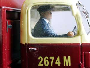
At this point I thought with everything in pieces it would be nice to install a driver before reassembling. I searched the market. Most drivers were loco drivers who had their arms set too low for the lorry driving position. I settled on a bus driver from Modelu (the most expensive supplier of unpainted figures!) because his arms were in a position likely to fit. My research discovered that 1950/60s British Railways lorry drivers were uniformed and wore a cap like all other railway staff so, with the bus driver wearing a similar cap I was encouraged that this might work.

Service from Modelu was quick with good communication. Sent out first class post it arrived 3 days later, delayed due to the postal service taking a holiday to celebrate the Queens jubilee!

The good, the bad and the ugly.

Good - The arm positions were perfect for the steering wheel position

Bad - The open leg positions were too far apart and too upright to fit the footwell

The Ugly - A very brittle material. With all the handling to get it to fit the lorry both drivers hands became amputated. They were rebuilt with blob layers of super glue bulked up with bicarbonate of soda sprinkles. In fact they do not look too bad compared the originals, which were not that well defined anyway.

What to do about the legs - I sawed off the legs at the knee and repositioned the lower limbs to be more forward, which left gaping holes behind the knees. These was filled with blob layers of super glue and BoS sprinkles, as for the hands. I initially thought I would need to fill with epoxy putty but the superglue method worked very well and set instantly. A little filing blended the fill with the resin legs.

With regard to painting, the current trend is to spray all over black and then spray white only from the direction of the sun. This leaves 'shadows' where the sun does not reach. I did the same, not with spray but with light brushing having wiped off most of the paint from the brush beforehand. Finally, the uniform and body parts were brush painted picking out the eye balls with a drop of paint on the end of a scalpel.

Now the tricky part - installation. Even with the lower legs moved forward he levitated above the seat. I had to cut away the footwell floor to allow his feet to lower so he could sit down. Then there was interference between his left hand and dashboard, impeding full insertion in the cab. That required filing away a little of the dashboard.

Originally the steering wheel column was located in the dashboard. Now, for the desired angle to fit the column, it was necessary to fit into a hole drilled in the footwell front wall.

Whilst all this jiggery-pokery was going on I succeeded in breaking off one of the sticky-outy wing mirrors. That was a shame because despite gluing it back on the repair is fragile and can be seen when looking for it.

By the way, the driver is held in place with double sided tape. His right hand in the photo (left) was the original. In the last photo it is the refabricated right hand. I fear I have compromised the lorry resale value with the changes made and damage incurred along the way.

I came across a close up photo of a driver in the cab of the full size lorry and am pleased to say that  my installation in the model is near identical. It filled me with delight as I reassembled the lorry knowing the driving position is correct and a driver is present.


Saturday, 13 February 2021

Lighting update for Corona Quay

Finally, I have illuminated the last two lamps on the layout. You should read this posting first to understand what this is about and why it has taken so long to finish the lamps.

Today I went for my Covid 19 inoculation and the place I had to go to was within half a mile of the Poundland shop where last year I bought the solar LED lighting for the layout lamps and buildings. I went in there to see if they had set up the garden products display (includes solar lights) that they had withdrawn to make way for Christmas products a few months ago. Indeed they had! Only two solar lights of the type I used before were on display, both of which I needed and bought. One for the lamps (see photo right) and an extra one for the Paper Mill.

More about the Poundland solar LED lamps. 

To an index of Corona Quay postings.

Friday, 5 February 2021

A Lorry for Corona Quay

My initial search only discoverd a couple of manufacturers of highly detailed 1:43 British lorries from the 1950-1970 period. I found the IXO Ford Thames ET6 in British Railways livery I felt that would be ideal. I bought a new model at a low price from an Ebay seller. In fact the range of prices for new models from a variety of Ebay sellers is quite wide at £30 to £70 for this truck. 

It looks the part but don't look too closely as it is left hand drive! Clearly IXO used  parts from their other continental models. I swapped the driving position and fitted a driver, which you can read about here.

To an index of postings about Corona Quay

Friday, 23 October 2020

Project 20 - 0 Gauge Layout - Part 31

Loading Gauge and Turnout lever barriers
I intended to enhance the road surface with puddles, crack repairs and weeds but looking at it now I do not feel the need to do so.

From a modelling aspect just a few more additions (see photos) then photography, movie production and play!

I am on the lookout for a detailed lorry of the period and I may add goods to the quay side.

END (for now)

Index of articles for this series:
(each open in a new window/tab)

Part 1:  Baseboard Construction

Part 2: Track Plan

Lifebouy
Part 3: DIY 3D Print Sleepered Rail

Part 4. Sleepered Turnout Construction  

Part 5: Power Feeds 

Part 6: Turnout Buried in Tarmac Construction

Part 7: Ballasting Track with Pumice

Part 8: Weathering Track

Part 9: More track layout and construction

Part 10:  Cassette Storage Fiddle Yard Construction

Part 11: SR Buffer Stop Construction

Part 12: LB&SCR Level Crossing Construction

Part 13: Scalescenes Free Hut for 0 Gauge 

Part 14. Scratchbuild Mc Boaty Marine Engineers Workshop 

Part 15. Modelling Flora

Part 16: DIY 3D Print Railings 

Part 17a to  Part 17b: Scratchbuild Hillson Paper Mill

Part 18: Second Fiddle Yard 

Part 19: Loco Driver & Fireman

Part 20: A Suprising Buffer Stop 

Part 21: Road and Wall Construction

Part 22. DIY 3D Print Quayside Crane 

Part 23: Scalescenes Puffer Boat in 0 Gauge

Part 24: Quayside Furniture Construction 

Part 25a to Part 25e: Scratchbuild Transshipment Shed and Goods

Part 26: Corona Quay Photo Survey

Part 27: Siding Power Isolation Switching 

Part 28: Lighting for Buildings

Part 29:  Cameo Scene Construction

Part 30:  Working Yard Lamp Construction


Wednesday, 14 October 2020

Project 20 - 0 Gauge Layout - Part 30

Working lamps for the quay needed careful planning. I decided on SR concrete, art deco style yard lampposts. The most critical consideration was to incorporate the wiring unobtrusively and realistically.

The light source is the Pondland solar light previously explored in Posting 28. This comprises a can of electronics and a string of four LEDS. There are two SR lamps per baseboard (4 lamps in all). Whilst these can be sourced from one solar light it would require a connection cable with plug and socket between baseboards. To avoid that I decided to use a solar light per baseboard, since they are inexpensive at a pound each!

Having no spare solar lights I  redeployed the solar light that was in the office. Fortunately, the office and two lamps share a baseboard, which means I can still use two LEDs for the office with the electronics for all hung beneath the baseboard. For the two lamps on the other baseboard I'll need to buy another solar light. Only trouble is the shop has withdrawn garden stock (including solar lights) to make room for Halloween and Christmas product lines. I'll have to wait until after Christmas and hope the same solar lights reappear on the shelves.

The SR yard lamp includes a cross beam and insulators for telephone cable routing and a ladder. In practice there is quite a bit of variety in ladder provision, either to the side or on the same face as the lamp holder. The height also varies. None seem to reach the telgraph wires and some don't seem tall enough to reach the lamp!

The model is made from six DIY 3D printed parts. These are post, crossbeam, lamp arm, lampshade, switch box and ladder. The concrete parts were sprayed with Halfords grey primer and then sponge dabbed with black, white, yellow and brown acrylic paint to give the mottled colour effect of concrete.

Wiring needs to be as thin as can be. The LEDS draw so little current that the diameter of wire is of no consequence. I used two lengths of 1/0.25 sleeved wire covered in green heatshrink sleeve of 1.5 mm ID shrinking to 0.6 mm ID.

 First, an LED was cut from the string and its wires folded back along the body. (This gives a bit of meat for soldering the connecting wires and minimises heat migration from the iron to the LED.) The wires are fed up under the LED and through a hole in the top of the lamp holder. (I have drawn the wires in the photo to show them up better.). No gluing is necessary in this assembly.

A sleeve is placed over the wires between lamp shade and lamp arm and the wires run along a groove in the arm and continue on through a diagonal hole in the post. The wires, covered in heat shrink sleeving, run down the side of the post (as the prototype) to a dummy switch box near the base and from this through the baseboard.

The bottom of the post has a wire fixing post installed that holds it firmly in the baseboard without glue. Therefore, the lamp post can be removed and laid down if required for servicing or baseboard transportation.

 To Part 31.

 To Part 1.


Wednesday, 7 October 2020

Project 20 - 0 Gauge Layout - Part 29

Regular readers following this series may have glimpsed in previous photographs some road barriers on the quay. This posting explains what it is all about.

Back in April 2019 I made my first 7mm scale wagon, a converted ballast wagon for the conveyance of Southern line-side huts. With future plans to build Corona Quay in mind I dreamt up a cameo scene to justify arrival of the huts.

These huts were manufactured by the Southern Railway concrete works at Exmouth Junction post 1947 and well into the British Railways Period.

The Permanent Way department ordered a set for Corona Quay and sent two ground workers there to prepare the area.

They marked out the space for the huts with chalk and a section of railings were removed for access to the Branch Line from the huts. They used this air compressor and jack hammer to break up the concrete footings of the railing posts. 


The huts were delivered and having prepared the ground the workers found themselves with nothing to do waiting for arrival of the railway crane to hoist the huts into position.
 
One of the men picked up his newspaper and retired to the wheelbarrow to while away the time whilst the other paced about looking into the distance for the long overdue crane. (This photo also shows the disturbed earth where the railing posts once stood.)


Compressor and tools: DIY 3D printed except jack hammer made up from electrical wire and wire sleeving with multistrand electrical wire for the air line.
 
Barriers: card boards in DIY 3D printed trestles. 

Wheelbarrow: A .stl file from Thingiverse, rescaled and set on a wire chassis.

Figures by Omen Miniatures. Man in wheelbarrow had his hat reprofiled from diesel driver hat to flat cap. 
 

Wednesday, 23 September 2020

Project 20 - 0 Gauge Layout - Part 28

 This is amazing. Continuing my quest for simple electrics how about this for lighting 0 gauge buildings? Bought from Poundland for £1 is a solar LED light.

The lens simply unscrews leaving the can with integrated electronics, solar panel, power switch and a string of four LEDs. 


Here it is installed in McBoatys Marine Engineers building: The LED string can be bent to any position and the can fits into the apex of the building roof completely unseen from the outside. No modification required. The can is temporarily held in place by a cardboard wedge allowing its removal for battery recharging in natural light. The LEDs give off white light.

Each building has its own installation. The downside to all this is having to remove the kit for battery recharging and unable to turn the lights on and off from outside the building. This could be overcome by extending The LED string so that the can is held off-stage for a more user-friendly installation.


Simply placed on the ground


Hung from a hook on a purlin


Placed on the floor. One for each level.


Quay lamp posts are to be considered later.


Wednesday, 16 September 2020

Project 20 - 0 Gauge Layout - Part 27

 I needed to isolate a couple of sidings in order to hold a loco on the layout whilst another is driven (analogue control). Those to be isolated are the middle tracks at the bottom and top of the layout shown in the photo.

The idea is to isolate the power to the bottom siding where the Terrier loco is held whilst the Class 33 and its wagons are driven from the Branch Line to the top siding. Power to the top siding is then isolated and power turned on to the bottom siding so that the Terrier can pick up the wagons and shunt them to other areas of the Quay.

I did not install the power switching at the track laying stage. I waited until after the track was buried in tarmac. There was some logic to this because all track sections are independently wired to a bus bar underneath the layout and there are no fishplates joining the sections. In theory all I had to do was disconnect a siding rail wire from the bus bar and fit a switch between the bus bar and floating wire; this being done for each of the two sidings in question.

Where to locate switches took some head scratching. The thing is, the layout can be operated from either side. A fixed control panel therefore, would not be appropriate. A control panel would need to be hand held. Furthermore, the layout is spread across two portable baseboards. This would need cabling with plug and socket between boards and an umbilical cable to the hand held controller. I went as far as making brackets for D type connectors before thinking this was going to defeat the objective of keeping electrics simple.

My final solution was to fit two switches for each siding, one to each baseboard side. The switch on the side of the layout that is not currently operated from is held off and the one on the operating side controls power to its siding.

The next issue was the decorative quayside wall. I did not want this spoiled with a thumping big toggle or push button switch. I choose a miniature sliding switch as being the most unobtrusive and instead of screw fixing it to the wall I fabricated a holding panel that is glued behind. If I ever wanted to reuse the switch I guess I could break the panel glue bond to retrieve the switch.
Switch located in line with the siding it controls.
A second parallel wired switch is located
directly opposite in the other side panel.

So far so good. With switches in place I tackled the wiring. Disconnecting the first siding wire from the bus bar I tested that the track rail was now isolated. It wasn't. Clearly the rail was touching the live rail of the next track section! How the hell was I going to resolve that now the track was nicely buried in tarmac!


I had to carefully razor saw at the rail join to break the connection which also left a saw cut in the tarmac - to be repaired. Thankfully, the rail join in the second siding was already isolated, as intended.

To Part 28.

To Part 1.

OK, why worry about a switch showing with
a large hinge in view? Good point.
(BTW. This hinge is at the non-
decorative fiddle yard end.)

Wednesday, 26 August 2020

Project 20 - 0 Gauge Layout - Part 26

I started this project in January 2020, before furlough became a word in common use. Throughout the Corona Virus pandemic building this model railway became a sanctuary for me to escape the worries and disturbing news of events impacting society. The model is not finished but has reached a point of visual acceptance.

The location is fictitious and consequently had no name. As time wore on it became obvious that only one name would be fitting. I can now reveal its identity.

Welcome to CORONA QUAY.


Thursday, 20 August 2020

Project 20 - 0 Gauge Layout - Part 25E

The roof slates are laid as overlapping rows and the entire roof is removable so that the highly detailed interior can be viewed more easily. Drainpipes are 3D printed.

I thought about adding canopies. This would not be appropriate for the ship loading side as rigging etc. would get in the way. For the lorry loading side a canopy would impede our view of the interior. In practice not all Goods Sheds were fitted with canopies.

Basic scenic details for the whole layout are now complete ready to run trains realistically. Future works will focus on small details such as telegraph poles, lamps, weeds, goods, people and lighting buildings. I also need to put in some isolating track wiring so that an engine can be held in a siding whilst another is run (analogue control).

The next Blog posting will reveal the name for this layout. Can you guess what it is?

To Part 26.

To Part 1.

Friday, 14 August 2020

Project 20 - 0 Gauge Layout - Part 25D

The photograph below shows cargo and handling equipment to be placed in the transhipment shed. All are 3D printed by myself.
  • 3 barrels; scaled up from 2mm designs I created for an N gauge layout. The ends carry labels identifying the whiskey content and destination address.
  • Oil Drum; scaled up from 2mm designs I created for an N gauge layout. The middle band has logos, as per the prototype.
  • Crates; scaled up from 2mm designs I created for an N gauge layout. They carry destination address labels
  • Associated Portland Cement (Blue Circle) Cement bags; designed for this project and carry printed paper logos.
  • Sack Truck; a free .stl from www.thingiverse.com. Had to be rescaled.
  • Pallet; a free .stl from www.thingiverse.com. Had to be rescaled.
  • Pallet Truck; a free .stl from www.thingiverse.com. Already to scale (1:43).
So pleased with the results Fixed down with blu tack as I wanted the option of  removing or repositioning them.
 To Part 25E.

Friday, 7 August 2020

Project 20 - 0 Gauge Layout - Part 25C

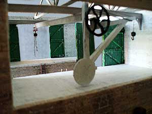
This is about lifting equipment for the transhipment shed. With platforms either side of the run through siding a beam hoist is necessary to convey goods from one to the other. The cabling is static but the trolley can be moved along the beam. Quite pleased how this turned out.

The beam is supported by two longitudinal beams that are mounted on wall brackets. All parts are 3D printed except cabling and pulley. I tried to print the pulley but it did not form as well as those on the Puffer Boat, perhaps because the elliptical Puffer pulleys have a bit more 'meat'. In my stock box I had a couple of small rods with spigots on the ends so it was made up from that.

The beam extends over the lorry loading area and you would think it would also extend over the boat loading area. Remembering this is a quay on a river estuary with coastal steamers visiting; I decided it would not be appropriate as it could get in the way of a boats rigging when it is trying to moor alongside. So, a rotating crane is installed on that platform.

This crane is a scaled up version of my 4mm scale goods shed crane. The design is fully detailed so no further enhancements were required for this larger version.

To Part 25D
.

To Part 1.


Tuesday, 28 July 2020

Project 20 - 0 Gauge Layout - Part 25B

What a (near) disaster!

Inside the transhipment shed there are two platforms either side of the siding. These were installed and the doors permanently fixed in the open position.

I then placed a wagon in the building to see how it all looked and discovered that I had made the platforms too tall such that hinged doors of wagons could not open due to interference. I decided to live with that error as the build had gone too far to correct this, so I thought.

Later, I noticed I had fixed the doors the wrong way around such that the framing faced outwards from the building! This was something I could not accept so I set about correcting it and the platform height.

The easiest way to reduce the height of the platforms was to reduce the height of the entire building by cutting a strip off the bottom of the walls. This was possible since there was more than enough clearance for rolling stock through the door openings.

First, I had to remove the doors. Fortunately, I had only tack glued them in place so with judicious use of a scalpel I separated them from the building. Inevitably some damage to their decorative surface occurred which was repaired by reprinting and overlaying a new decor.

Next, armed with a hacksaw blade I carefully cut a strip from the bottom of the walls.

Reviewing the relationship between rolling stock and the lowered platform I felt it may still be too high. I then researched the height of goods platforms and discovered there was no common standard with heights varying between regions and eras. One comment I came across suggested the height would be level with the wagon floor. On checking the model I found this was close to what I had set. Phew!

Door bottoms were trimmed to match the new building height and fixed in place again.

The photo above shows the result.

The building shell is covered with decorated stone paper inside and out. The inside stonework is the same artwork as the outside except the brightness is reduced to look like white washed walls. There is quite a lot of acreage that dissuaded me from painstakingly applying a second layer of individual stones for relief.

To Part 25C
.

To Part 1.


Wednesday, 22 July 2020

Project 20 - 0 Gauge Layout - Part 25A

The final building is a transhipment shed placed at the far end of the layout. It has a railway siding running through it and out to a fiddle yard. Therefore, it is possible to propel a fully loaded open wagon into the shed and off stage to the fiddle yard where the load is removed and the empty wagon propelled back through and out of the shed as though it was unloaded in the shed.

I have to say I am struggling with lack of enthusiasm for this build. There are two issues at play. The first is that this is a fictitious building, albeit having architectural features taken from a variety of real buildings. I much prefer modelling complete real world buildings but found nothing that fitted the location on the layout. The second issue is that I wanted to give an impression of the building being longer than depicted with part of it being off stage.

The first building 'shell' I made had the loading doors off set from centre with the large quayside door opening extending to the wall at the fiddle yard end thereby giving the impression of a longer building. The illusion did not work. So, I decided what you see is the entire size of the building with door openings centralised. I feel a bit better about it now.

Note that the walls are made from corrugated packaging board, as is usual for this layout.

To Part 25B.

To Part 1.

Wednesday, 15 July 2020

Project 20 - 0 Gauge Layout - Part 24

The quay wall now looks complete and authentic having added the following fittings.

3D printed bollards. There is a wide variety of styles used in the real world. This one looks too tall but is scaled from a dimensioned drawing of a prototype.


Ladders are 3D printed with wire handrails. Modelled from a photograph of a real installation..

The railway siding between the quay wall and the paper mill is close to the edge so a protective railing is installed. It is 3D printed in two parts glued together. It printed at the first attempt better than I expected.

Wednesday, 8 July 2020

Project 20 - 0 Gauge Layout - Part 23

What to do about this -


It is the hinge mechanism that joins together the portable baseboards. It needs disguising during operations. My first thought was to cover it by extending the quay wall forward in that area with a removable wall - simple but boring. What would be better is to place a cargo boat in front of it. Not only would it cover the hinge but add interest to the scene. After all, a quay should include a tethered boat.

So, I made this.

It is the Scalescenes downloadable card kit of a Clyde Puffer.

Now, I thought I was making a model railway but for the past few weeks I have researched and built a boat!

I wanted a small cargo boat and this was the best inexpensive model kit I came across. £5.99 + ink and materials.

The first hurdle to overcome was the period of the model. Clyde Puffers in their original form did not survive in commercial use to the 1960s (The period of my model railway). However, during the 1940s The Admiralty ordered a number of Puffers. After the war those that were still serviceable were sold off for commercial use and some survived into the 1960s and beyond. I looked through the lists of Victualling Inshore Craft (VIC), as they were known, and selected VIC 24, as this is reported as being on the south coast in the 1960s renamed Advance. What use it was put to I don't know.

The next hurdle to overcome was the kit itself. The Scalescenes offering is for an 00 or N gauge model not 0 gauge. Every component of the 00 gauge kit (and there are a lot) had to be scaled up to 0 gauge (a factor of 1.75). This entailed using a graphic editing Application to cut each component from the original .pdf pages and then scale up. A few components extended to A3 paper size. Either they needed cutting at an unobtrusive point to fit A4 or cut an A3 sheet of paper to A4 wide for top feeding in my A4 printer. I used both techniques.

The 00 gauge kit requires 3 thickness of card and board (0.15ish, 1mm and 2mm). Scaling up to 0 gauge (0.2ish, 1.75 and 3.5) corrugated packing box board was used for the thickest. This worked well with the corrugations entirely hidden during construction.

The kit has adequate details to pass as a 'Puffer' for railway modellers but there are some notable omissions covered by a supplementary enhancement instruction .pdf available freely from the product listing on their web site. I strongly recommend applying the enhancements. Even so, there are still small details evident on the prototype that are not included. Furthermore, there appears to be subtle differences between builds of the prototype! For a boat enthusiast wanting a detailed and faithful model of the prototype then this may not be the kit choose. Further research would be needed to faithfully model a specific prototype. I have seen some very fine, highly detailed scratch built Puffer models on the web.

Having studied photographs of VIC24 I included some details specific to that Puffer but the most significant discrepancy is the width of the wheelhouse, which stretches to the full width of the deckhouse on the prototype. On the Scalescenes model it is narrow like the original Puffer prototype builds.

My 3D printer was brought into play again to fabricate the davit, pulleys, vents, railing uprights, anchor and ladders. Ropes were made from tightly twisted electrical wire.

The final hurdle was to devise a way of suspending the boat against the quay wall and be removable. I decided to make a platform depicting a stretch of water on which to place the boat. The platform is made from corrugated cardboard with water made from toilet paper, paint and gloss cork tile sealer. Tutorial here. The platform temporarily fixes to the quay wall by means of three cocktail stick 'skewers'.

Well, the boat is a bit heavier than expected and caused the platform to droop. This could have been a show stopper. I had to find a way of temporarily fixing the boat to the quay wall but without introducing obtrusive fixings.

The solution was hinged latches mounted on two of the pilings. When not in use they fold down out of the way.


In use they are lifted up, the boat placed and then let down over the bulwark of the boat.


Now I need to add mooring bollards on the quay and tethering ropes.

Related Posts Plugin for WordPress, Blogger...