About Comments

Comments are enabled on all postings. Click a posting to find the comment box. Comments are moderated and appear after my review.

Saturday, 14 November 2020

Trees for a Grandson's Train Set

 Photo shows the autumn flowering Sedum ' Autumn Joy'.

Wait until winter to harvest the dead flower stalks then PVA glue some together to form a posy that looks like a tree. Some sprigs are set into the bunch at an angle to help form the tree shape. I glued one sprig at a time waiting for the glue to set between placements. It takes quite some time to complete. A different, instant setting glue would speed up the process.

Spray the dead flower heads with green acrylic paint, maybe a dark shade and then lighter shade where the light falls. I made a wooden template same size as the area destined for the trees and arranged five trees in a group. I drilled holes in the template to accept the tree trunks. (I made the template because the trees were made miles away from the train set.)

The template was placed on the train set and holes drilled into the baseboard through the template holes. The trees were then pushed into the holes without the need for glueing.


Friday, 23 October 2020

Project 20 - 0 Gauge Layout - Part 31

Loading Gauge and Turnout lever barriers
I intended to enhance the road surface with puddles, crack repairs and weeds but looking at it now I do not feel the need to do so.

From a modelling aspect just a few more additions (see photos) then photography, movie production and play!

I am on the lookout for a detailed lorry of the period and I may add goods to the quay side.

END (for now)

Index of articles for this series:
(each open in a new window/tab)

Part 1:  Baseboard Construction

Part 2: Track Plan

Lifebouy
Part 3: DIY 3D Print Sleepered Rail

Part 4. Sleepered Turnout Construction  

Part 5: Power Feeds 

Part 6: Turnout Buried in Tarmac Construction

Part 7: Ballasting Track with Pumice

Part 8: Weathering Track

Part 9: More track layout and construction

Part 10:  Cassette Storage Fiddle Yard Construction

Part 11: SR Buffer Stop Construction

Part 12: LB&SCR Level Crossing Construction

Part 13: Scalescenes Free Hut for 0 Gauge 

Part 14. Scratchbuild Mc Boaty Marine Engineers Workshop 

Part 15. Modelling Flora

Part 16: DIY 3D Print Railings 

Part 17a to  Part 17b: Scratchbuild Hillson Paper Mill

Part 18: Second Fiddle Yard 

Part 19: Loco Driver & Fireman

Part 20: A Suprising Buffer Stop 

Part 21: Road and Wall Construction

Part 22. DIY 3D Print Quayside Crane 

Part 23: Scalescenes Puffer Boat in 0 Gauge

Part 24: Quayside Furniture Construction 

Part 25a to Part 25e: Scratchbuild Transshipment Shed and Goods

Part 26: Corona Quay Photo Survey

Part 27: Siding Power Isolation Switching 

Part 28: Lighting for Buildings

Part 29:  Cameo Scene Construction

Part 30:  Working Yard Lamp Construction


Tuesday, 13 October 2020

Project 20 - 0 Gauge Layout - Part 30

Working lamps for the quay needed careful planning. I decided on SR concrete, art deco style yard lampposts. The most critical consideration was to incorporate the wiring unobtrusively and realistically.

The light source is the Pondland solar light previously explored in Posting 28. This comprises a can of electronics and a string of four LEDS. There are two SR lamps per baseboard (4 lamps in all). Whilst these can be sourced from one solar light it would require a connection cable with plug and socket between baseboards. To avoid that I decided to use a solar light per baseboard, since they are inexpensive at a pound each!

Having no spare solar lights I  redeployed the solar light that was in the office. Fortunately, the office and two lamps share a baseboard, which means I can still use two LEDs for the office with the electronics for all hung beneath the baseboard. For the two lamps on the other baseboard I'll need to buy another solar light. Only trouble is the shop has withdrawn garden stock (including solar lights) to make room for Halloween and Christmas product lines. I'll have to wait until after Christmas and hope the same solar lights reappear on the shelves.

The SR yard lamp includes a cross beam and insulators for telephone cable routing and a ladder. In practice there is quite a bit of variety in ladder provision, either to the side or on the same face as the lamp holder. The height also varies. None seem to reach the telgraph wires and some don't seem tall enough to reach the lamp!

The model is made from six DIY 3D printed parts. These are post, crossbeam, lamp arm, lampshade, switch box and ladder. The concrete parts were sprayed with Halfords grey primer and then sponge dabbed with black, white, yellow and brown acrylic paint to give the mottled colour effect of concrete.

Wiring needs to be as thin as can be. The LEDS draw so little current that the diameter of wire is of no consequence. I used two lengths of 1/0.25 sleeved wire covered in green heatshrink sleeve of 1.5 mm ID shrinking to 0.6 mm ID.

 First, an LED was cut from the string and its wires folded back along the body. (This gives a bit of meat for soldering the connecting wires and minimises heat migration from the iron to the LED.) The wires are fed up under the LED and through a hole in the top of the lamp holder. (I have drawn the wires in the photo to show them up better.). No gluing is necessary in this assembly.

A sleeve is placed over the wires between lamp shade and lamp arm and the wires run along a groove in the arm and continue on through a diagonal hole in the post. The wires, covered in heat shrink sleeving, run down the side of the post (as the prototype) to a dummy switch box near the base and from this through the baseboard.

The bottom of the post has a wire fixing post installed that holds it firmly in the baseboard without glue. Therefore, the lamp post can be removed and laid down if required for servicing or baseboard transportation.

 To Part 31.

 To Part 1.


Wednesday, 7 October 2020

Project 20 - 0 Gauge Layout - Part 29

Regular readers following this series may have glimpsed in previous photographs some road barriers on the quay. This posting explains what it is all about.

Back in April 2019 I made my first 7mm scale wagon, a converted ballast wagon for the conveyance of Southern line-side huts. With future plans to build Corona Quay in mind I dreamt up a cameo scene to justify arrival of the huts.

These huts were manufactured by the Southern Railway concrete works at Exmouth Junction post 1947 and well into the British Railways Period.

The Permanent Way department ordered a set for Corona Quay and sent two ground workers there to prepare the area.

They marked out the space for the huts with chalk and a section of railings were removed for access to the Branch Line from the huts. They used this air compressor and jack hammer to break up the concrete footings of the railing posts. 


The huts were delivered and having prepared the ground the workers found themselves with nothing to do waiting for arrival of the railway crane to hoist the huts into position.
 
One of the men picked up his newspaper and retired to the wheelbarrow to while away the time whilst the other paced about looking into the distance for the long overdue crane. (This photo also shows the disturbed earth where the railing posts once stood.)


Compressor and tools: DIY 3D printed except jack hammer made up from electrical wire and wire sleeving with multistrand electrical wire for the air line.
 
Barriers: card boards in DIY 3D printed trestles. 

Wheelbarrow: A .stl file from Thingiverse, rescaled and set on a wire chassis.

Figures by Omen Miniatures. Man in wheelbarrow had his hat reprofiled from diesel driver hat to flat cap. 
 

Tuesday, 22 September 2020

Project 20 - 0 Gauge Layout - Part 28

 This is amazing. Continuing my quest for simple electrics how about this for lighting 0 gauge buildings? Bought from Poundland for £1 is a solar LED light.

The lens simply unscrews leaving the can with integrated electronics, solar panel, power switch and a string of four LEDs. 


Here it is installed in McBoatys Marine Engineers building: The LED string can be bent to any position and the can fits into the apex of the building roof completely unseen from the outside. No modification required. The can is temporarily held in place by a cardboard wedge allowing its removal for battery recharging in natural light. The LEDs give off white light.

Each building has its own installation. The downside to all this is having to remove the kit for battery recharging and unable to turn the lights on and off from outside the building. This could be overcome by extending The LED string so that the can is held off-stage for a more user-friendly installation.


Simply placed on the ground


Hung from a hook on a purlin


Placed on the floor. One for each level.


Quay lamp posts are to be considered later.


Wednesday, 16 September 2020

Project 20 - 0 Gauge Layout - Part 27

 I needed to isolate a couple of sidings in order to hold a loco on the layout whilst another is driven (analogue control). Those to be isolated are the middle tracks at the bottom and top of the layout shown in the photo.

The idea is to isolate the power to the bottom siding where the Terrier loco is held whilst the Class 33 and its wagons are driven from the Branch Line to the top siding. Power to the top siding is then isolated and power turned on to the bottom siding so that the Terrier can pick up the wagons and shunt them to other areas of the Quay.

I did not install the power switching at the track laying stage. I waited until after the track was buried in tarmac. There was some logic to this because all track sections are independently wired to a bus bar underneath the layout and there are no fishplates joining the sections. In theory all I had to do was disconnect a siding rail wire from the bus bar and fit a switch between the bus bar and floating wire; this being done for each of the two sidings in question.

Where to locate switches took some head scratching. The thing is, the layout can be operated from either side. A fixed control panel therefore, would not be appropriate. A control panel would need to be hand held. Furthermore, the layout is spread across two portable baseboards. This would need cabling with plug and socket between boards and an umbilical cable to the hand held controller. I went as far as making brackets for D type connectors before thinking this was going to defeat the objective of keeping electrics simple.

My final solution was to fit two switches for each siding, one to each baseboard side. The switch on the side of the layout that is not currently operated from is held off and the one on the operating side controls power to its siding.

The next issue was the decorative quayside wall. I did not want this spoiled with a thumping big toggle or push button switch. I choose a miniature sliding switch as being the most unobtrusive and instead of screw fixing it to the wall I fabricated a holding panel that is glued behind. If I ever wanted to reuse the switch I guess I could break the panel glue bond to retrieve the switch.
Switch located in line with the siding it controls.
A second parallel wired switch is located
directly opposite in the other side panel.

So far so good. With switches in place I tackled the wiring. Disconnecting the first siding wire from the bus bar I tested that the track rail was now isolated. It wasn't. Clearly the rail was touching the live rail of the next track section! How the hell was I going to resolve that now the track was nicely buried in tarmac!


I had to carefully razor saw at the rail join to break the connection which also left a saw cut in the tarmac - to be repaired. Thankfully, the rail join in the second siding was already isolated, as intended.

To Part 28.

To Part 1.

OK, why worry about a switch showing with
a large hinge in view? Good point.
(BTW. This hinge is at the non-
decorative fiddle yard end.)

Tuesday, 8 September 2020

East Anglia Transport Museum

I always try to visit a heritage railway when on holiday but where we were staying in south east Norfolk there was not one close by. We did find the East Anglia Transport Museum at Carlton Colville near Lowestoft

Famed for working trolley buses and trams they also have a narrow gauge railway. The diesel locomotives came from quarry or industrial workings and the passenger coaches were made at the museum.

We were very lucky that our holiday coincided with the first day of opening since lockdown (currently only open Sunday and Thursday afternoons). No need to book and pay in advance (unlike many other venues during the pandemic). Just turn up and hope they have not had to close the gate due to capacity being reached. I thought it would be crowded on the first day of opening but it was not and I don't think anyone was turned away. I was told the visitor numbers were typical for a Sunday when fine weather encourages people to visit nearby Lowestoft beach instead of the museum.

The museum occupies a small site with a large variety of vintage vehicles, mostly housed in reproductions of vintage garages. An adjacent field has been purchased to expand the museum to more than double its current size.

One vehicle that caught my attention was a Thornycroft J class lorry, many miles from its Basingstoke manufacturer base. These are very rare today, despite over 5000 being manufactured in the early years of the 20th Century. I understand the engine has been restored to working order and further bodywork restoration is in progress.

It caught my attention because I modelled the J class for our Thornycroft Sidings N gauge layout

A trolley bus built in the 1950s and a 1927 tram that once operated in Blackpool were offering rides during our visit. 

Another surprise for me was trolley bus number 696 (built in 1938) showing a Dartford destination, Dartford being my home town during my childhood years. I vaguely remember trolley buses in Dartford but buses I travelled on to go to school were of the modern kind.

This museum is well worth a visit and I would go again when in the area.

Tuesday, 25 August 2020

Project 20 - 0 Gauge Layout - Part 26

I started this project in January 2020, before furlough became a word in common use. Throughout the Corona Virus pandemic building this model railway became a sanctuary for me to escape the worries and disturbing news of events impacting society. The model is not finished but has reached a point of visual acceptance.

The location is fictitious and consequently had no name. As time wore on it became obvious that only one name would be fitting. I can now reveal its identity.

Welcome to CORONA QUAY.


Wednesday, 19 August 2020

Project 20 - 0 Gauge Layout - Part 25E

The roof slates are laid as overlapping rows and the entire roof is removable so that the highly detailed interior can be viewed more easily. Drainpipes are 3D printed.

I thought about adding canopies. This would not be appropriate for the ship loading side as rigging etc. would get in the way. For the lorry loading side a canopy would impede our view of the interior. In practice not all Goods Sheds were fitted with canopies.

Basic scenic details for the whole layout are now complete ready to run trains realistically. Future works will focus on small details such as telegraph poles, lamps, weeds, goods, people and lighting buildings. I also need to put in some isolating track wiring so that an engine can be held in a siding whilst another is run (analogue control).

The next Blog posting will reveal the name for this layout. Can you guess what it is?

To Part 26.

To Part 1.

Friday, 14 August 2020

Project 20 - 0 Gauge Layout - Part 25D

The photograph below shows cargo and handling equipment to be placed in the transhipment shed. All are 3D printed by myself.
  • 3 barrels; scaled up from 2mm designs I created for an N gauge layout. The ends carry labels identifying the whiskey content and destination address.
  • Oil Drum; scaled up from 2mm designs I created for an N gauge layout. The middle band has logos, as per the prototype.
  • Crates; scaled up from 2mm designs I created for an N gauge layout. They carry destination address labels
  • Associated Portland Cement (Blue Circle) Cement bags; designed for this project and carry printed paper logos.
  • Sack Truck; a free .stl from www.thingiverse.com. Had to be rescaled.
  • Pallet; a free .stl from www.thingiverse.com. Had to be rescaled.
  • Pallet Truck; a free .stl from www.thingiverse.com. Already to scale (1:43).
So pleased with the results Fixed down with blu tack as I wanted the option of  removing or repositioning them.
 To Part 25E.

Thursday, 6 August 2020

Project 20 - 0 Gauge Layout - Part 25C

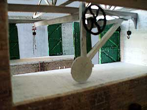
This is about lifting equipment for the transhipment shed. With platforms either side of the run through siding a beam hoist is necessary to convey goods from one to the other. The cabling is static but the trolley can be moved along the beam. Quite pleased how this turned out.

The beam is supported by two longitudinal beams that are mounted on wall brackets. All parts are 3D printed except cabling and pulley. I tried to print the pulley but it did not form as well as those on the Puffer Boat, perhaps because the elliptical Puffer pulleys have a bit more 'meat'. In my stock box I had a couple of small rods with spigots on the ends so it was made up from that.

The beam extends over the lorry loading area and you would think it would also extend over the boat loading area. Remembering this is a quay on a river estuary with coastal steamers visiting; I decided it would not be appropriate as it could get in the way of a boats rigging when it is trying to moor alongside. So, a rotating crane is installed on that platform.

This crane is a scaled up version of my 4mm scale goods shed crane. The design is fully detailed so no further enhancements were required for this larger version.

To Part 25D
.

To Part 1.


Monday, 27 July 2020

Project 20 - 0 Gauge Layout - Part 25B

What a (near) disaster!

Inside the transhipment shed there are two platforms either side of the siding. These were installed and the doors permanently fixed in the open position.

I then placed a wagon in the building to see how it all looked and discovered that I had made the platforms too tall such that hinged doors of wagons could not open due to interference. I decided to live with that error as the build had gone too far to correct this, so I thought.

Later, I noticed I had fixed the doors the wrong way around such that the framing faced outwards from the building! This was something I could not accept so I set about correcting it and the platform height.

The easiest way to reduce the height of the platforms was to reduce the height of the entire building by cutting a strip off the bottom of the walls. This was possible since there was more than enough clearance for rolling stock through the door openings.

First, I had to remove the doors. Fortunately, I had only tack glued them in place so with judicious use of a scalpel I separated them from the building. Inevitably some damage to their decorative surface occurred which was repaired by reprinting and overlaying a new decor.

Next, armed with a hacksaw blade I carefully cut a strip from the bottom of the walls.

Reviewing the relationship between rolling stock and the lowered platform I felt it may still be too high. I then researched the height of goods platforms and discovered there was no common standard with heights varying between regions and eras. One comment I came across suggested the height would be level with the wagon floor. On checking the model I found this was close to what I had set. Phew!

Door bottoms were trimmed to match the new building height and fixed in place again.

The photo above shows the result.

The building shell is covered with decorated stone paper inside and out. The inside stonework is the same artwork as the outside except the brightness is reduced to look like white washed walls. There is quite a lot of acreage that dissuaded me from painstakingly applying a second layer of individual stones for relief.

To Part 25C
.

To Part 1.


Tuesday, 21 July 2020

Project 20 - 0 Gauge Layout - Part 25A

The final building is a transhipment shed placed at the far end of the layout. It has a railway siding running through it and out to a fiddle yard. Therefore, it is possible to propel a fully loaded open wagon into the shed and off stage to the fiddle yard where the load is removed and the empty wagon propelled back through and out of the shed as though it was unloaded in the shed.

I have to say I am struggling with lack of enthusiasm for this build. There are two issues at play. The first is that this is a fictitious building, albeit having architectural features taken from a variety of real buildings. I much prefer modelling complete real world buildings but found nothing that fitted the location on the layout. The second issue is that I wanted to give an impression of the building being longer than depicted with part of it being off stage.

The first building 'shell' I made had the loading doors off set from centre with the large quayside door opening extending to the wall at the fiddle yard end thereby giving the impression of a longer building. The illusion did not work. So, I decided what you see is the entire size of the building with door openings centralised. I feel a bit better about it now.

Note that the walls are made from corrugated packaging board, as is usual for this layout.

To Part 25B.

To Part 1.

Tuesday, 14 July 2020

Project 20 - 0 Gauge Layout - Part 24

The quay wall now looks complete and authentic having added the following fittings.

3D printed bollards. There is a wide variety of styles used in the real world. This one looks too tall but is scaled from a dimensioned drawing of a prototype.


Ladders are 3D printed with wire handrails. Modelled from a photograph of a real installation..

The railway siding between the quay wall and the paper mill is close to the edge so a protective railing is installed. It is 3D printed in two parts glued together. It printed at the first attempt better than I expected.

Related Posts Plugin for WordPress, Blogger...