About Comments

Comments are enabled on all postings. Click a posting to find the comment box. Comments are moderated and appear after my review.

Thursday, 30 May 2024

Project 24 - Battledown Flyover #8 (end of phase 1)

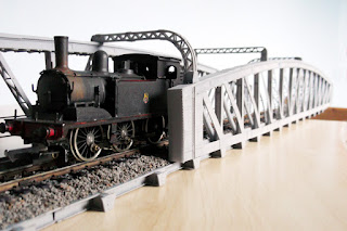
Considering phases of this project then this is the end of phase 1 in so far as all the 3D printing is complete. Next phase is the brick pillars, which will employ a different modelling medium. The final phase will be integrating the bridge into a landscape.

The last 3D prints to make and apply were the three top spanning girders. I am glad it is over because the manufacturing process is complex, messy and time consuming but frankly, there is no better DIY way of making a model with such high level of detail comprising thousands of rivets!

Track ballast has also been applied. This is sieved pumice grit with a sprinkling of cork granules for colour variation. Ballast is fixed in the traditional way of laying it dry and then flood with a 50:50 mix of PVA glue and water with a drop of washing up liquid to ease surface tension so that it flows easily through the ballast. When dry a black wash was applied to the track bed between the rails.

The bridge looks the part when viewed from the sides (normal viewpoint) but looking end on there is some bowing of the sides. I found it difficult to keep the sides flat as the cured resin took on a life of its own. As I have mentioned before the water washable resin used is not really tough enough to hold the shape of a model this size where thin sections are present.

By the way, the loco chimney does clear the spanning girders with about 5 mm gap.

To Part 9.

To Part 1.

Friday, 24 May 2024

Project 24 - Battledown Flyover #7 (track progress)

The track needed lifting by 1 mm on the bridge deck to mirror the level of the prototype. The obvious method was to use cork sheet as this may also absorb the sound from 'toy' trains as they pass over the bridge. 1mm thick cork was duly bought off Ebay but, what arrived was 4 mm thick! 

Evidently the vendor had no stock of 1mm (despite their listing showing stock available) and thought 4 mm would do! Well, I got a refund and searched for another supplier and I also wondered if I had anything that could substitute for it.

Right in front of my eyes on my desk was a spare sheet of 1.5 mm thick corrugated cardboard. Since this had air pockets then it too might be suitable as a sound absorber. In fact, a test with and without cork or corrugated board had no effect on sound absorption (probably too thin). Anyway, the corrugated cardboard was cut to size and glued in place using Copydex latex glue.

On top of the cardboard a paper track template was glued down to guide adjustment of the double sleeper sections of the track, which was glued on top using Copydex. Copydex with a little heat allows easy removal of track for reuse in the future.

The masking tape shown in the above photo was to preserve the raw plastic surface for later gluing in place the bridge sides.

My method of painting the track was to spray a mix of burnt umber and black acrylic paint (colours that I had to hand) then wipe off the overspray from the rail top.

When dry the cosmetic fishplates were glued each side of the rail at the joins

A mix of brown, yellow and red to mimic rust was hand painted along the side of the rails and over the chairs. The fishplates being picked out in black.


Wednesday, 15 May 2024

Project 24 - Battledown Flyover #6 (track prep)

In the early 1960s the track style at Battledown Flyover was quite different to that of today. Both the Salisbury and Southampton lines used wooden sleepers but their chair style differed. (incidentally no third rail). The Southampton down line was fitted with BR1 chairs and Spikes. I guess the up line was too although I have not seen photo evidence for it. The Salisbury line was fitted with BR3 chairs comprising a lip to hold the outer edge of the running rail, with a single baseplate screw to secure the outer side of the baseplate to the sleeper.  The inside of the rail and baseplate were secured with two spikes. Track was made from 60 foot flat bottom rail joined by four bolt fishplates and there were 24 sleepers per section.

Looking around at what stock I have there is a bit of Peco code 100, that is already allocated to something else but could be reclaimed for this project. There is more Graham Farish Formoway code 100 available, though not enough to build a layout so, I'll use this and buy more from the after market if needed.

When I rebuilt Misterton in code 75 bullhead I 3D printed the sleepers and chairs using my FDM printer for greater accuracy of chair style than R.T.R. track offered at the time. I am doing the same again, this time using my Resin printer to make flat-bottom rail sleepers and chairs. For the rail I'll strip it from my GF track.

I started with the BR1 design and lost count of the number of trials to get it to fit the rail smoothly. I measured the rail foot to be 1.9 mm wide. The 'trough' for the foot was eventually set at 2.08 mm. I think the failures were due to me not leaving sufficient clearance (by the way, the Peco rail foot is 2.3mm wide so, my chairs will not fit that brand).

I also designed and printed cosmetic four bolt fishplates.

The photos do not give justice to the fine details. With a magnifying glass the bolts and wood grain are clearly seen!

To Part 7.

Sunday, 12 May 2024

Project 24 - Battledown Flyover #5 (disaster recovery)

The floor is in four parts. At the front of the photo is the East End and above it one of the centre sections.

The East End was printed first. The deck sides cracked and broke away as I removed the resin support structure and the deck surface is rippled and pitted. Both defects are not a show stopper because they are hidden when the bridge is assembled.

For printing, the part was angled 10 degrees for both X and Y. This is my usual setting. After further research I learnt that models with a large flat area are best printed at 45 degrees. This was set for the centre section and to my surprise fewer supports were created by Lychee and the deck printed without ripples. However, it still suffered from fractures of the deck sides and now the trapezoid plates as well. I could fabricate some infills so, still viable.

It was at this point I test fitted the deck to the two bridge sides and discovered to my horror that the width of the deck is too narrow compared to the prototype. It needs an extra 10mm. Well that was a show stopper. I had to rework the design to widen the deck and at the same time I doubled the thickness of the deck and trapezoid plates in the hope they would not fracture.

The East End floor was reprinted and came out much cleaner, except for some deformation of the bottom girder flanges, which can be corrected with plastic infills. The deformation is due to inadequate supports at the ends so, I added more to the East End floor and centre section designs. The reprinted centre section formed perfectly.

I am having doubts about using water washable resin due to its brittleness. Also, the usual method of leaving the dirty water in full sun for a couple of days to let the resin cure and fall out of the water is not too successful. The water tends to hold onto the resin. I believe IPA would separate itself more readily and whilst IPA can be used instead of water if I went that way I would probably move to a more pliable resin as well.

To Part 6


Friday, 10 May 2024

Project 24 - Battledown Flyover #4 (full span)

Here is the full span, having joined the three parts together.

It was at this point I came across an article that cited the length as being 145 feet, not 150 feet that I had estimated. If the article is right then in 4mm scale the span is 20 mm too long! Too late now, this lot took about 39 hours to print and I am not repeating the exercise. I will plough on to print the other side, then the floor and then the three girders that go across the top.

To Part 5.


Saturday, 4 May 2024

Project 24 - Battledown Flyover #3 (centre span anomalies)

There is something odd about the angled struts in the centre span of the bridge seen today.

Looking left  to right:

Strut 1, whilst having cross bracing like some of the others, is unique in that its sides are not double thickness.

Strut 2 and 5 have riveted plate bracing instead of cross bracing.

Strut 3 has riveted plated bracing as 2 & 5 but it also has an angle bracket riveted to its sides that the other two do not have.

Struts 4, 6, 7 & 8 are identical all having cross bracing and double thickness sides.

I spent a long time meticulously designing the model in this respect and when done (and before printing, thankfully) I looked back over some photographs from the 1960s (my model era) and discovered two significant differences in finish and design.

  1. The paint scheme was battleship grey and not the dark green of today (nice - grey stands out in the landscape making the bridge look even more impressive).
  2. All the angled struts of this centre section were identical, being the same design as strut 1 above.
Had I known this before designing the centre span it would have been a much simpler task. The only saving grace is strut 1 which, was simply replicated and mirrored to replace struts 2 to 8.

I think that the struts were modified/changed to reinforce the structure. I have seen photographs of the bridge in 1967 that show scaffolding across the centre span. The struts were of the current implementation and the bridge grey. Either the scaffolding was there to paint the bridge or inspect / reengineer the struts, I guess.

With regard to the end spans the west end strut 2 has double thickness sides but, not in the 1960s. That is the only difference between the two ends. I had already printed the ends so, I had to file off the riveted plate from strut 2 to reflect the 1960s version.

Here is the printed centre span with 1960s style struts. It is a simpler design proposition requiring consistently styled struts.

I am using Anycubic water washable resin for convenience. The downside is the plastic is very brittle and easily broken/snapped. However, it breaks cleanly and takes Superglue well to make invisible repairs. Other grades of resin are available that are more pliable but they require IPA as a cleaning medium*.

* Evidently there is a tougher ABS like resin that is water washable although some reports indicate, whilst a little more pliable it also breaks easily.


Related Posts Plugin for WordPress, Blogger...