About Comments

Comments are enabled on all postings. Click a posting to find the comment box. Comments are moderated and appear after my review.
Showing posts with label ballast cleaning train. Show all posts

Wednesday, 10 April 2024

Ballast Cleaning Train - Part 19 (SLA Resin 3d Print Version)

 This is the final part for this project.

Matisa 3B5 Ballast Cleaning Machine (late 50s early 60s BR era)

Aerial view of the machine and its electric generator wagon

How they were coupled for travelling.
In operation the generator was coupled to the other
end of the machine and an electrical cable connected between them.

Sunday, 7 April 2024

Ballast Cleaning Train - Part 18 (SLA Resin 3d Print Version)

Photo shows the cabins for both wagons and two other bits for the generator wagon after a spraying with black gloss car paint.

Why black for wagons that are to be finished in 1960s departmental yellow? Black is a common base for figurine painting as it enhances shadows caused by creases in clothing when overpainted to let the black through in places. The same principal is applied here except there is so little relief in these parts that shadows are minimal. Furthermore, I found that it changed the hue of the final yellow coating requiring multiple layers to recover. I will not use black for the remaining parts of this build. However, it was useful in simulating the rubber surround of the window panes that were revealed when the masking tape was removed.

It was really difficult to emulate the yellow colour of the prototype. The Railmatch 2304 I chose was far too yellow. My first approach was to tone it down with a white wash.  This made it too pale so I followed up with a brown wash that brought it as close to prototype as I could achieve.

There are seven components that are resin printed, including the chassis with all its levers, rods, axle boxes, leaf springs etc. printed as one piece. The railings are galvanised wire, the couplings Hornby, the wheelsets proprietary, the lights are ends of a biro ink tube with polystyrene gell glue infilled and the vacumn pipes are wire with thinner wire wound around. These could have been integrated with the chassis print.

Here is a comparison between the FDM printed model (background) and resin printed model (foreground).  For the uninitiated there does not seem to be much difference. But there is!

First, we may notice the colour change. The FDM paint finish is completely wrong having a green tinge. Next is a difference in equipment. I believe the resin model is more representative of the picture in the book and an early period photo I used for reference. The equipment on the other is based on a later version that was photographed in a yard awaiting scrapping.

Other notable differences where the resin printed model wins over FDM:
  • No visible print layers
  • Finer details e.g. axle boxes and leaf springs fully formed - as good as injection moulded. (For the FDM model I butchered a proprietary wagon and implanted its injection moulded axle box and leaf springs to achieve detail.)
  • Sharper corners and edges
  • Fewer parts
All the parts for the ballast cleaning machine have been printed and painted. Assembly next, which will be featured in the next blog posting.


Wednesday, 27 March 2024

Ballast Cleaning Train - Part 16 (SLA Resin 3d Print Version)

There is a lot that could go wrong with the design and print of this generator wagon chassis. For a start there is a lot of thin levers, rods and brackets in the underframe that may not print well. Then, there is the distance between axle boxes; did I get it right taking into account fitting of brass axle bearings and free running wheels.

Well, the print (6hrs 42 mins) was near perfect. The only damage was a few breakages as I cut away the intense support structure. (I think the Lychee auto support facility goes OTT on quantity but, it is a godsend for the novice.) Plasticard infills repaired the breakages.

One mistake was to use a hairdryer to quickly dry off the print after water washing. The heat warped the axle box tie bars badly. The print is quite pliable prior to UV curing so, I used various materials with required thicknesses to prop and force the tie bars as straight as possible before the UV curing process. The UV then hardens the plastic allowing parts to hold their shape. The tie bars were much improved although a little warping is still present that I'll have to live with. I really don't want to reprint the model.

The wheel sets fitted perfectly between the axle boxes. However, they did not turn freely. I had made a big design mistake by setting the brake shoes too close to the wheel treads and flanges. The brakes were locked on! I had to snip off the break shoes, cut the brake rods back a little and re-glue the shoes in place. Did I say I really don't want to reprint the model. (It uses a lot of resin and takes too long.)

Talk about printed detail - the individual leaves of the leaf springs are clearly visible! Each leaf must be no more than a quarter millimeter thick.

Postscript: I had a eureka moment about the warped tie bar. I glued a piece of stiff wire behind the tie bar which pulled the bar straight.

Tuesday, 26 March 2024

Ballast Cleaning Train - Part 15 (SLA Resin 3d Print Version)

 Printer worked flawlessly this time.

Here are the cabins for the ballast cleaning machine and generator wagon plus two more components (print time 7hrs 42mins). Once again some fine details visible.

The cabin on the left has two hand rails replaced with copper wire because I knocked the printed ones off whilst removing supports. The auto support generator facility of the Lychee Slicer Application was a bit over ambitious there stuffing the rails with unnecessary supports that were hidden by other supports  (and on the printed model). I could not see them in the Application to manually adjust but, have since found out how and have adjusted the offending ones.

I believe there is just one more model to print and that is the generator wagon chassis.


Monday, 25 March 2024

Ballast Cleaning Train - Part 14 (SLA Resin 3d Print Version)

Change of plan. 

I like to be around during the print to keep a check on things - and it is a good job I did (more on that later). It is a case of knowing when I am available against time needed for a print run so, the cabin mentioned previously is deferred in favour of others.

First up are the conveyors (print time 6hr 50mins). Two needed a reprint due to inadequate support structure and even after further optimisation the third one down in the photo has a deformed end. Fortunately this will be hidden when assembled so no problem. Removing the support structure is fraught with difficulty as it is easy to break elements of the model. In this case plasticard implants saved the day (e.g. the white part on the right hand end of the nearest conveyor).

On checking the print progress I was alarmed to see the print had paused and an error message on the screen saying the USB stick was disconnected. It seems for each print layer the program reads the file on the USB stick memory rather than importing the file to internal memory for processing. The error message included an instruction to reinsert the USB stick. Having done this the print resumed exactly where it left off without any damage to the finished model. That is impressive! However the same problem arose 4 or 5 times early in the printing cycle before it settled down.

This event has been reported by others. I have not found the cause but it could be due to one of three reasons, programming fault, dodgy contacts or unstable USB stick. I changed the USB stick and the next print run was faultless. But, my confidence was a little shaken and now feel I must monitor print runs periodically.

The next print was the girder frame (print time 9hr 42 mins). This model is extremely delicate and needed a mass of supports, many in awkward places making them difficult to remove. Great care is needed. 

I am pleased to say there were no deformations!

I was really impressed with the quality of this model, especially due to its complexity.

The hand rails (photo below) prove that this technology is ideal to achieve fine details. They are only 0.5mm diameter with a 0.5mm gap to the girder.


To Part 15.

Wednesday, 20 March 2024

Ballast Cleaning Train - Part 13 (SLA Resin 3d Print Version)

I was not totally satisfied with my FDM 3D printed ballast cleaning wagon models, due to lack of detail, plastic layers evident and design errors. This lead me to buying an SLA 3D printer, which gives injection moulded quality without the high development cost.

This series of posting is as much about my experience as a novice in this technology as the development of the model.

I started with the ballast cleaning machine to be followed later by the generator wagon. Potentially the model could be printed as one piece instead of the 60 odd parts made on the FDM printer. However, I am aware that invariable it is not until the SLA printer has done its work that we can review the finished model for flaws and since the process takes many hours then a serious flaw in the model results in wasted time and materials. In view of this I split the model into about 20 parts. (I do know that tools are available to assess the model for flaws before it is printed)

For efficiency the build plate of the SLA printer should be filled with parts as the printing time is dictated by model height rather than number of models on the build plate. As a novice I expected failures so, to avoid waste I limited the number of parts.

First, I produced a small batch of odd ball parts. Their .stl files were loaded into Lychee slicer software and the automatic support feature activated to create the essential support structure. The output file was loaded into the printer and print started. 3.5 hours later the prints were ready and yes, one of the parts failed. The first oil drum in the photo has a split and is deformed. This was solely down to inadequate supporting structure. This one's support structure was different to the others. I simply copied that of a good model and printed again satisfactorily.


1st attempt with support structure
Next was a more complex model - the ballast cleaning machine chassis. After 5.5hrs the chassis was ready. Yes, there were flaws. They did not look too damaging but as there were quite a few deformations and I accidently broke off some of the steps I decided to strengthen the steps in the design, review the support structure and print again. Quickly I learnt that the support structure is critical and the automatic support generating feature of Lychee is not a panacea for success. The deformations helped me in understanding where more supports are needed and these were manually added. 


2nd attempt

After washing uncured surface resin away the support structure is severed from the model using snips. Great care is needed in doing this because delicate elements are easily damaged - and this did occur. Thankfully a spot of Superglue worked well to stick back damaged parts.

There were still some very minor deformations that I can live with, except one place being more noticeable. I did not want to print again so I filled the gap with a piece of plasticard filed to fit. I also accidently knocked off the edge of the buffer bean (This stuff is very brittle) which was corrected with more plasticard.

I am very pleased with the quality of finish. Surfaces are smooth, very small parts well formed and rivets that I added to the buffer beam in the design are visible.

Next to prepare and print is the cabin.

To Part 14.

Read about the SLA resin 3D printer here.

Read about the FDM model here.


Saturday, 16 September 2023

Ballast Cleaning Train - Part 12

This is the final part of this series about modelling in 4mm scale a 1960 BR(S) ballast cleaning train.

Here is the movie!


To follow this series from the start go to Page 1.

This may not be the end of the story because I am correcting and detailing further the CAD files of the ballast cleaning and power generator wagons with a view to (maybe) 3D resin printing the models for greater finesse.

Ballast Cleaning Wagon Chassis (CAD resin model)

Friday, 8 September 2023

Ballast Cleaning Train - Part 11

Fitting a Zero 1 chip to the T9 Locomotive

I use the Hornby Zero 1 system to control trains. It is an early type of DCC (1980s). If all you want is simple track wiring and the ability to operate multiple locos at the same time then there is no cheaper option. Parts are available from the after market. The down side is that the chip is big and will not fit some modern model locomotives.

We need to open the Tender to fit the chip. My T9 has a six wheeled tender. There is also a 4 wheel variant. These instructions may not be suitable for that one.

  1. Disconnect the loco plug from the tender socket and remove the tender from the loco. Remove the two screws that are located near the chassis sides between the two rear sets of wheels and lift the body from the rear to release it from the tag holding it at the front
  2. Remove the three weights (we need the space!). I found removing weights does not not affect performance

3. Position the chip on top of the pickup strips. When reassembling it may be necessary to  adjust its position to achieve fit of body to chassis


4. Note the position of pin 1 marked on the plugin and remove the plugin; then mark pin 1 on the 8 way socket board. Set aside the plugin. It must not be used for this procedure.
5. Take a piece of solid wire about same thickness as the pins on the plugin. Form a 'U' and insert it in positions 1 and 8. Solder the chip black wire to this. 
6. Strip and tin the red and green wires. Poke the green wire into position 4.
7. Solder the capacitor that came with the chip to the 'U' loop of wire and poke the other end into position 5 (not shown in photo)
8. Solder the red wire to this capacitor leg (position 5). Ensure the capacitor legs do not touch other positions. If necessary, insulate the legs with the sleeve stripped from other wire
9. Reconnect the loco white plug to the tender white socket and test loco operation.
10. Refit the tender body locating the front tag first.

The loco crew were taken from an old Airfix Permanent Way Figure set. There is not a lot of room in the cab, certainly they cannot stand side by side. The lack of space is due to the boxes set against each cab side wall. These are wider than the prototype because they have to accommodate the 00 gauge rear driving wheels, which are set closer together than the prototype.


Sunday, 3 September 2023

Ballast Cleaning Train - Part 10

The staff coach associated with this train was an ex-SE&CR 60 ft. Birdcage Brake 3rd lavatory (BTL) coach. These coaches (and non lavatory versions) were taken into departmental stock after they were withdrawn from passenger duties. Initially they were not repainted. Later the departmental colour of black and later still drab olive green was deployed and the coach re-numbered into the DS series.

I found two references to coaches used in BR(S) Departmental Stock:

  • BTL SR 3479 in Malachite was assigned to Matisa Ballast Cleaner DS100 in November 1956.
  • BTL SR 3521 in Malachite renumbered to DS 136
I cannot tell from the 1960 monochrome photos of the train what livery it had at that date nor the number allocation.

Model coaches are available from Bachmann (RTR) and Roxey Mouldings (KIT). Ever mindful of the cost I choose Bachmann from the after market. Bachmann coaches are available in Malachite, Olive, Dark Lake and Crimson. Some colours are only available from the after market.

At first I though to repaint a coach if I could find one that was in less than perfect condition but, all seemed to be new or in pristine condition. I am reticent about repainting a pristine model and as I don't know what livery it had in 1960 I decided not to repaint (for the time being). On this basis I should go for the Malachite version but this has extensive decals making it obvious for passenger services. The Crimson version is the only one with minimal decals and if I did repaint then it will be a simpler job to do.

The Bachmann Crimson is currently only available from the after market. I bid in an EBAY auction for one and lost out, being the underbidder. The person who won was very keen and placed multiple bids. If I had bid more I am sure I would have been outbid again. It sold for £31 + postage. 'Buy it now' prices for these Crimson coaches vary widely, anything from £40 to £75. I went for the cheapest EBAY 'Buy it now' coach available at £40 + postage - and whilst stated as 'used' it is in pristine condition.


Friday, 25 August 2023

Ballast Cleaning Train - Part 9

I previously bought two unpainted Dapol grampus wagons that accompanied this train with a view to painting them weathered black, not realising that the Dapol unpainted model is already black! I decided to leave them as is and just fit the numbering. I choose a couple of DB numbers from the Eastleigh allocation since the train shown in the books was on its way to Eastleigh depot. The assumption being that the ballast cleaner was stabled there(?)

The lettering was printed on sticky paper labels and when stuck on the model the white edges were carefully blacked with a fine tipped pen. 

In the book Southern Steam in Action 1 there is a close up photo of the leading grampus in this train. Two 'oil' drums and a ladder are clearly visible in the wagon. Other bits and bobs there are not identifiable. I 3D printed the loads using some of my own designs and some 3D .stl crate designs from Thingyverse.


The second wagon appears in another photo of the same train in Southern Steam from Lineside. It is far too distant to see the load clearly but looks like it contains more bits and bobs. I chose to retain the ballast load supplied with the Dapol wagon on the basis that when the spoil is taken out the remaining cleaned ballast may need to be supplemented. The unpainted (black) wagon load was sprayed with grey primer and then lightly sponge dabbed with brown, white and black acrylics to represent the colour variation of Meldon ballast.

Friday, 18 August 2023

Ballast Cleaning Train - Part 8

There were two major considerations in the design of the final spoil conveyor.

1. Negotiating model track curves.

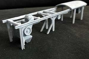
It is obvious that this long conveyor sticks out a long way from the rear of the wagon. If the conveyor was fixed in position then, with the wagon in transit and moving around track curves especially the tight curves of model railway track, it would swing out beyond loading gauge limits and potentially hit a train on an adjacent track. Therefore, I had to make it swivel (as the prototype) so that it can be constrained within the width of the wagons.  An added complication is the hopper that feeds this conveyor. It cannot be fixed to the conveyor. We can see the split line in the photo that allows the conveyor to swivel independently of it.

When designing the conveyor I had to ensure its height kept within the loading gauge and ensure there was no interference with parts of the generator wagon. These constraints set the length of the conveyor. 

The conveyor rests on a yoke frame. I raised the ends of this to limit travel of the conveyor as the train  negotiates track curves. I am pleased to say that the swivelling conveyor works as planned around the tightest curves of my model railway layout. 

2. Interaction with the Power Generator Wagon

As explained, the conveyor rests on the Generator Wagon during transit. Well, that is how it was in the early days. Later on the machine was supplied with a match truck where the conveyor rested on that instead. 

I digress here to explain the orientation of the two wagons. In the photo above the arrangement is for transport. For working activities the power generator wagon is run around the other end of the machine and a high voltage umbilical cable connected between the cabins.

Whilst I digress, how does the ballast cleaning machine move when working? Beneath the buffer stock at the spoil conveyor end is a drum winch with two cables. The cables may have been bolted to the fishplates or chairs of the railway track and the machine winched itself incrementally along. Another oddity is the braking arrangement of the machine. I have found no evidence of brakes or vacuum pipes on this early machine. Maybe the red handles beneath the cabin operated brakes(?) What there is is a long pipe that runs along the girder frame to the buffer stocks at each end. I guess that connected to the pipes of adjacent wagons?

Now, there are subtle differences between between builds of this Matisa 3B5 machine and the generator wagon variant I choose to model seems to be a latter variant that did not support the conveyor (match truck used instead?). Consequently that big box on the end of the wagon causes the conveyor to lift higher than desired and this lead to it being shorter that in should be. The variant I should have modelled did not have the big box. Instead it had two fuel drums laid down and further inboard that would allow the conveyor slope to be less and its length longer so that it sat correctly above the generator unit instead of in front of it.

In Conclusion

I had hoped to get the design of these models right first time but, I'm afraid I have not. I have a list of 10 faux pas of which the most significant is the girder frame that should have been set further in board. Correcting this will have knock on effects of many other parts.  Modelling the wrong generator wagon variant is also disappointing. Also, I am unhappy with the quality of 3D print. It all looks a bit rough on close inspection. Nevertheless, when I placed the models on my scenic model railway they certainly look the part and we do not notice the rough finish as much. So, I am encouraged to carry on with this project.

What I will do is overhaul the CAD design to correct errors and add more details with a view to Resin 3D printing in the future for greater finesse of the models.

Next though I must prepare the Grampus wagons.

To Part 9.

To Part 1.


Saturday, 12 August 2023

Ballast Cleaning Train - Part 7

The vibrating sieve box and first spoil expulsion conveyor have been added. When the spoil reaches the end of the conveyor it drops into the hopper and onto the final conveyor, which is the next part to be modelled.

If you stumbled upon this individual posting and wondered what this mess of parts is then best first go and watch it in action at YouTube here.

To Part 8.

To Part 1.

Saturday, 5 August 2023

Railway Ballast Cleaning Train - Part 6

It looks like a diesel shunter but, in fact is a 440V electrical power generator wagon for the ballast cleaning machine conveyor motors etc.

There are more details to add to this wagon that will have to wait because there are dependencies on parts of the ballast cleaning wagon that are not yet modelled. In particular, its spoil expulsion conveyor that rests on top of the generator during transportation.

The black radiator grill has a close mesh effect that was created using a trick of the 3D printer. When it prints thick parts it prints a honeycomb for internal layers to save on plastic and print time. I simply programmed it to continue printing the honeycomb through to the outer layer instead of finishing with a solid layer. Parameters of the honeycomb can be manipulated to give the desired close mesh effect.

The two lamps required some ingenuity to make from bits to hand. They were made from the clear end of a Bic biro ink tube and the dome formed by filling the hole with polystyrene cement gel. I was pleased with the outcome until closer inspection of the prototype showed them as being oblong!.


Saturday, 29 July 2023

Railway Ballast Cleaning Train - Part 5

Now it is beginning to look like something interesting albeit bizarre! 

The long sloping down arm is the excavator in its 'parked' position. There is another one on the other side. These were lowered and pulled out to the ballast shoulder. First though the ballast must be cleared manually (I assume) from between two sleepers down to the substrate because the two excavators are joined at their base by a removable section that goes under the rails. Contained in the arms is a continuous chain driven series of blades that collect and push the ballast to and up the furthest arm as the vehicle moves slowly along the track. I'll explain later how that was done as the machine is not self powered. At the apex of the arms the ballast falls onto a conveyor (the sloping up piece) that moves it to the sieve (not yet modelled).

I am pleased how well the 3D printer created the chain driven blades. I designed these as separate components with their blades attached to a thin wall (the chain), the flexibility of which allowed it to be bent around the curve at the base of the excavator arms.

The  excavator 'motor' is positioned high up and pokes above the girder frame. Understanding its shape and fixings was extremely difficult to glean from photographs as it is not clearly detailed but, eventually I got the drift and whilst not totally correct to prototype (there is a mass of girders etc. up there that are not modelled) it looks ok and gives the impression it could work. 

The conveyor belt came out well. The printer decided to give it a slight ripple in places that gives the impression of a floating, flexible belt. Colouring of this was done with black pastel scrapes.

This was an intense design period so, I'll return to the simpler Power Generator wagon next for a mental break.

In fact, there are another two more intense design periods for the ballast cleaning wagon before it is done. These being the sieve mechanics and spoil expulsion.


Saturday, 22 July 2023

Railway Ballast Cleaning Train - Part 4

Having spent ages scrutinising photographs of the prototype I think I have finally worked out the principal of operation and how the ballast was handled within the machine. Initially I thought ballast cleaning meant the ballast was picked up, washed and put back down. Not the case at all! The principle of machine operation is simple; ballast is excavated from beneath the track and conveyed to a vibrating sieve where anything smaller than the 'rocks' falls through the sieve and is either conveyed to open wagons stationed alongside or, spewed onto the adjoining landscape. The remaining 'cleaned rocks' are returned to the track bed. The complication comes in understanding how materials are moved through the machine.

Having made the chassis for the model I decided to populate it from bottom up. The most significant addition is the 'ballast distribution conveyor'. In the photograph it is the long thing with holes beneath the chassis. Either side of the holes are rollers for the conveyor belt (not in the model of course - here they are a crude representation). 

This conveyor is the last process in the cleaning operation. It is shown on the model stored for transportation. In operation it is pivoted down and manually swung side to side to distribute the cleaned ballast to the track bed.

Why does ballast need cleaning? Over time the content of the track bed is corrupted with dirt and other particles that could lead to destabilisation of the track bed, meaning the natural locking of the ballast rocks is disturbed.

I have also completed the cab that sat at one end of the machine. I do not know what was inside. I guess it contained controls. 

The paint finish I made up from yellow and brown acrylics to get as close as I can to the 'grubby' yellow used by BR for these machines in the late 1950s to early 60s.

The design of these models goes beyond mirroring the prototype. I also have to take into account the foibles of the FDM 3D print machine. I intended to print the cab as one piece but that would have shown the layers of plastic requiring much sanding down (in fact the first photo above shows the effect). In the end each side and roof were printed separately with the outside faces being the first plastic layer set down on the smooth printer bed. The lines of plastic are much less visible this way. Not the case for the roof where the corrugated effect due to plastic layering was covered in superglue and bicarbonate of soda sprinkles and then sanded smooth.

I have been spoiled by the incredible finish and details of current ready to run models from the trade. My 'scratch build' is rough but, possibly acceptable at normal viewing distances. Reminds me of RTR proprietary models from the 40s and 50s, which were also a bit naïve!

To Part 5.

To Part 1.


Saturday, 15 July 2023

Railway Ballast Cleaning Train - Part 3

Why did I pause the ballast cleaning wagon design and build to start its associated power generator wagon? Well, the design of the former is intense and potentially exhausting. At the end of it would I then be motivated to start all over again with the power generator wagon? By turning attention now to the latter is refreshing and seeing both develop together reminds me that the two wagons are inseparable in practice.

The power generator wagon has fixed wheel sets located in axle boxes hung from the chassis together with leaf springs. These include quite detailed parts; very small in 4mm scale that FDM (fused deposition modelling) printing cannot reproduce well. Fortunately, I had available a scrapped kit built wagon with detailed injection molded parts precisely matching the prototype. These, including a portion of sole bar they were fixed to, were cut from the donated wagon and inserted in the sole bar of the power generator wagon. BTW, brake blocks were also reclaimed.

Inserted axle box - final
Now, the sole bar of the donated wagon is not as tall as the new wagons so, the axle box etc. had to be offset in the new sole bar to be flush with its base. When I placed the new wagon on the track the buffer line was at least 1 mm higher than other wagons! This is not much, but glaringly wrong. Here we go again, 2 steps forward and one back. The parts had to be cut from the new sole bar and its height reduced to match before replacing them. Razor saw cuts were filled with superglue and bicarbonate of soda sprinkles to give a solid infill then filed smooth.

Weathering was applied with brown pastel scrapes (appears grey in photo)

I am impressed with the levers and hangers that printed better than expected. Vacuum pipes were made from solid copper wire with thinner wire wound around.


I'll return to the other wagon design and build next.

To Part 4

To Part 1

Friday, 7 July 2023

Railway Ballast Cleaning Train - Part 2

This project is turning out to be very fulfilling with periods of  excitement and anticipation as I research, design and build the two ballast cleaning vehicles for this train. So much so that I have been up at 5 am to spend most of the day on the project. There is also periods of frustration, not too many though. It feels a bit like two steps forward and one back, as is often the case in product development.

Not much to show for my efforts in this posting as a lot of the time is spent on research at this stage. Any how, I now have the chassis designed and 3D printed for the cleaning machine. This is the simplest part. I do not have a clue how the design of machine parts used for ballast cleaning will turn out - they are quite complicated.

The two grampus wagons for the train have arrived. I was a bit too hasty in purchasing these. I think I was influenced in seeing that traders stocks appeared quite low so wanted to be sure I got them. In fact, I purchased the last two in stock at Hattons. I wanted black wagons, being the colour for engineers trains in the 1960s. I did not initially see these for sale so, I opted for the Dapol unpainted variety. Thinking they would be a neutral grey I was pleased to see on arrival that they were already black, which saves on the paint job, although I may apply weathering. They will need appropriate numbers added of course. It was then that I found fully finished black wagons were also available, albeit a few pound more expensive. If I buy transfers for numbering the wagons then the total cost will be about the same!

The wagons come with a ballast load. These are not needed for this train as they were loaded with a variety of objects, including ladder and oil drums. Fortunately, the ballast load is not fixed and was easily removed.

My brake van is an old Airfix kit that I may change for the more detailed R.T.R. model.

To Part 3

To Part 1

Sunday, 2 July 2023

Railway Ballast Cleaning Train - Part 1

Little Bro' kindly gifted me a Hornby T9 no. 30313. This is a loco I always fancied but had not got around to obtaining. I had in the back of my mind for some time making up the ballast cleaning train that I saw in 'Southern Steam from Lineside' page 69. The photo portrayed the train as (in order) T9 30729, 20T grampus wagon, ex-SE&CR 'birdcage' BCL or BT staff coach (have not worked out which yet), A Matisa 3B5 (or variant) ballast cleaning machine with separate electric power generator wagon, another grampus and a 20T brake van. A close up view of the same train (front end only) appears in 'Southern Steam in Action 1' page 36. Matisa, a Swiss company, supplied the 3B5 to British Railways in the 1950s and it remained in service into the 1960s.

Watch it in action at YouTube.

I already have a brake van. I have ordered two Dapol unpainted Grampus wagons that I'll paint rusty black. I'll purchase the coach later. However, its livery for departmental use was likely a dark green. R.T.R. model coaches do not depict this. The ballast cleaning machine is a very complex piece of kit that is not available in model form from the trade. I'll need to make one which, is the subject of this posting series.

After much research on the web I have gathered a number of photos to work from. (Example:  http://www.leedsmrs.org/jpegs/Gallery/AlanSmith/P/Ponteland%20plant%20exhib%20Matisa%20Ballast%20Cleaner%201961.jpg). Being photographed on a track bed allowed the track sleeper pitch of about 2.5 feet to be used for scaling purposes. However, the 'jumble' of machine parts are in an open frame making it difficult to understand function and form. Therefore, my model cannot be accurate to prototype, it being just an interpretation.

Having made rolling stock before I always start with the wheel bogies (or underframe for fixed wheel sets). The bogies were designed in 3D CAD and 3D Printed (FDM) in three parts that were glued together. The coupling is by Hornby and wheel sets are from my spares box. For wheel bearings I found some electronics, brass terminal posts in my spares box that have mounting cylinder posts just about the right size. These were cut off and pressed into the side frames.


Wheel Bearings


To Part 2

Read about the SLA resin 3D print version here.


Related Posts Plugin for WordPress, Blogger...