About Comments

Comments are enabled on all postings. Click a posting to find the comment box. Comments are moderated and appear after my review.

Sunday 21 April 2024

Project 24 - Battledown Flyover #1 (preamble)

Having successfully completed my first Resin 3D print project I was considering what to create next. The thing about Resin 3D printing is its ability to produce miniscule, crisp details. This drives us to go the extra mile in model design. In particular, as far as railways are concerned - rivets. Yes, I have become a rivet counter! 

Within walking distance of my home is Battledown Flyover - The Gateway to the West. It carries the up line from Southampton whilst the Salisbury up & down lines pass underneath, at a slew.

Battledown Flyover by Sandy B, CC BY-SA 2.0,
via Wikimedia Commons

If I modelled this scene where could I put it? My railway room is overflowing with layouts. 

My Misterton model railway layout in its current form has existed since 2016, having evolved from an earlier incarnation dating from the 1980s with the station building and goods shed created in the 1970s! It is based on 1960s Crewkerne station in Somerset, England. It being a main line station with goods handling facilities. 

I realised that from an operational point of view it mainly gets used to run trains round and round for the enjoyment of grandchildren. Shunting and Goods Yard operations are as rare as hens teeth. This might be the time to replace it with the Battledown Flyover scene. It would be exciting to see a train running over the flyover whilst another passes underneath.

I am a bit hesitant abandoning a station scene but, I do have a small branch line layout that maybe could be placed somehow on the other side of the oval. I am not sure at this stage whether a new layout will come to fruition. But, a flyover model diorama is certain, if only to make use of my 3D printer and satisfy my creative soul.

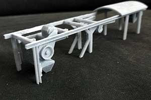
I researched the web and books, gathering images of the flyover and visited it several times to photograph elements of it. When I saw the beast close up I was taken aback by its complex construction and use of riveted plate girders. So many rivets! Its construction is compounded further by the struts not all being the same design. Some have different form (why?) and width meaning each need to be tweaked or designed independently for the model. I'll answer that question in a future posting.


Wednesday 10 April 2024

Ballast Cleaning Train - Part 19 (SLA Resin 3d Print Version)

 This is the final part for this project.

Matisa 3B5 Ballast Cleaning Machine (late 50s early 60s BR era)

Aerial view of the machine and its electric generator wagon

How they were coupled for travelling.
In operation the generator was coupled to the other
end of the machine and an electrical cable connected between them.

Sunday 7 April 2024

Ballast Cleaning Train - Part 18 (SLA Resin 3d Print Version)

Photo shows the cabins for both wagons and two other bits for the generator wagon after a spraying with black gloss car paint.

Why black for wagons that are to be finished in 1960s departmental yellow? Black is a common base for figurine painting as it enhances shadows caused by creases in clothing when overpainted to let the black through in places. The same principal is applied here except there is so little relief in these parts that shadows are minimal. Furthermore, I found that it changed the hue of the final yellow coating requiring multiple layers to recover. I will not use black for the remaining parts of this build. However, it was useful in simulating the rubber surround of the window panes that were revealed when the masking tape was removed.

It was really difficult to emulate the yellow colour of the prototype. The Railmatch 2304 I chose was far too yellow. My first approach was to tone it down with a white wash.  This made it too pale so I followed up with a brown wash that brought it as close to prototype as I could achieve.

There are seven components that are resin printed, including the chassis with all its levers, rods, axle boxes, leaf springs etc. printed as one piece. The railings are galvanised wire, the couplings Hornby, the wheelsets proprietary, the lights are ends of a biro ink tube with polystyrene gell glue infilled and the vacumn pipes are wire with thinner wire wound around. These could have been integrated with the chassis print.

Here is a comparison between the FDM printed model (background) and resin printed model (foreground).  For the uninitiated there does not seem to be much difference. But there is!

First, we may notice the colour change. The FDM paint finish is completely wrong having a green tinge. Next is a difference in equipment. I believe the resin model is more representative of the picture in the book and an early period photo I used for reference. The equipment on the other is based on a later version that was photographed in a yard awaiting scrapping.

Other notable differences where the resin printed model wins over FDM:
  • No visible print layers
  • Finer details e.g. axle boxes and leaf springs fully formed - as good as injection moulded. (For the FDM model I butchered a proprietary wagon and implanted its injection moulded axle box and leaf springs to achieve detail.)
  • Sharper corners and edges
  • Fewer parts
All the parts for the ballast cleaning machine have been printed and painted. Assembly next, which will be featured in the next blog posting.


Wednesday 3 April 2024

Ballast Cleaning Train - Part 17 (SLA Resin 3d Print Version)

Spent some time viewing tutorials on weathering to learn a method for the two chassis.

First stage was grey primer even though one recommendation was not to bother because the plastic base will take acrylic paints and the more layers of paint that are applied the more the definition of fine details will be lost.

However, the next layer was not acrylic. It was gloss black car paint that I had to hand and this needs a primer. The finish gave the models an ex works pristine appearance.


Before applying weathering a spray of matt varnish is necessary to dull the gloss and give good adhesion for the weathering layers. The varnish I purchased was Pebeo Auxiliary Matt Varnish which, due to a mix up, was not the one I intended to buy. I intended to buy a rattle can but this one is for brush application and has a white appearance in the bottle. At first I was not at all sure if it would be suitable. Anyway I mixed 50:50 with water and sprayed a test piece. It quickly dried giving the required matt finish and also suppressed the black intensity to a dark grey which is also what I wanted.

The first weathering layer was a wet on wet application of watery mid grey paint. What this means is water is brushed over the model and then paint applied which runs into crevices for highlighting and gives a mottled effect on flat areas.

The light grey areas in the photo are where masking tape has been removed. Those areas are for gluing the superstructure in place. 

The next layer is various coloured, scraped pastel sticks (powders) brushed onto the chassis sides. This final effect was quite pleasing until I sprayed with an artists fixer compound to seal the powders. It glossed the surface and suppressed the powder colours! I remedied with more powder covering and left it like that. Not quite as good as the pre fixer coating.

The Generator Wagon has footboards painted the same colour as the superstructure. The closest match to that seen in prototype photographs that I found was Railmatch 2304 Early Warning Yellow. However, once applied it looked too bright so a wash of watered down white was brushed over. It is still not right. But, who is to say old photographs accurately portray colour anyway.

Monday 1 April 2024

A Card Kit for April


Swanage Coal Stage and Inspection Pit

Wednesday 27 March 2024

Ballast Cleaning Train - Part 16 (SLA Resin 3d Print Version)

There is a lot that could go wrong with the design and print of this generator wagon chassis. For a start there is a lot of thin levers, rods and brackets in the underframe that may not print well. Then, there is the distance between axle boxes; did I get it right taking into account fitting of brass axle bearings and free running wheels.

Well, the print (6hrs 42 mins) was near perfect. The only damage was a few breakages as I cut away the intense support structure. (I think the Lychee auto support facility goes OTT on quantity but, it is a godsend for the novice.) Plasticard infills repaired the breakages.

One mistake was to use a hairdryer to quickly dry off the print after water washing. The heat warped the axle box tie bars badly. The print is quite pliable prior to UV curing so, I used various materials with required thicknesses to prop and force the tie bars as straight as possible before the UV curing process. The UV then hardens the plastic allowing parts to hold their shape. The tie bars were much improved although a little warping is still present that I'll have to live with. I really don't want to reprint the model.

The wheel sets fitted perfectly between the axle boxes. However, they did not turn freely. I had made a big design mistake by setting the brake shoes too close to the wheel treads and flanges. The brakes were locked on! I had to snip off the break shoes, cut the brake rods back a little and re-glue the shoes in place. Did I say I really don't want to reprint the model. (It uses a lot of resin and takes too long.)

Talk about printed detail - the individual leaves of the leaf springs are clearly visible! Each leaf must be no more than a quarter millimeter thick.

Postscript: I had a eureka moment about the warped tie bar. I glued a piece of stiff wire behind the tie bar which pulled the bar straight.

Tuesday 26 March 2024

Ballast Cleaning Train - Part 15 (SLA Resin 3d Print Version)

 Printer worked flawlessly this time.

Here are the cabins for the ballast cleaning machine and generator wagon plus two more components (print time 7hrs 42mins). Once again some fine details visible.

The cabin on the left has two hand rails replaced with copper wire because I knocked the printed ones off whilst removing supports. The auto support generator facility of the Lychee Slicer Application was a bit over ambitious there stuffing the rails with unnecessary supports that were hidden by other supports  (and on the printed model). I could not see them in the Application to manually adjust but, have since found out how and have adjusted the offending ones.

I believe there is just one more model to print and that is the generator wagon chassis.


Monday 25 March 2024

Ballast Cleaning Train - Part 14 (SLA Resin 3d Print Version)

Change of plan. 

I like to be around during the print to keep a check on things - and it is a good job I did (more on that later). It is a case of knowing when I am available against time needed for a print run so, the cabin mentioned previously is deferred in favour of others.

First up are the conveyors (print time 6hr 50mins). Two needed a reprint due to inadequate support structure and even after further optimisation the third one down in the photo has a deformed end. Fortunately this will be hidden when assembled so no problem. Removing the support structure is fraught with difficulty as it is easy to break elements of the model. In this case plasticard implants saved the day (e.g. the white part on the right hand end of the nearest conveyor).

On checking the print progress I was alarmed to see the print had paused and an error message on the screen saying the USB stick was disconnected. It seems for each print layer the program reads the file on the USB stick memory rather than importing the file to internal memory for processing. The error message included an instruction to reinsert the USB stick. Having done this the print resumed exactly where it left off without any damage to the finished model. That is impressive! However the same problem arose 4 or 5 times early in the printing cycle before it settled down.

This event has been reported by others. I have not found the cause but it could be due to one of three reasons, programming fault, dodgy contacts or unstable USB stick. I changed the USB stick and the next print run was faultless. But, my confidence was a little shaken and now feel I must monitor print runs periodically.

The next print was the girder frame (print time 9hr 42 mins). This model is extremely delicate and needed a mass of supports, many in awkward places making them difficult to remove. Great care is needed. 

I am pleased to say there were no deformations!

I was really impressed with the quality of this model, especially due to its complexity.

The hand rails (photo below) prove that this technology is ideal to achieve fine details. They are only 0.5mm diameter with a 0.5mm gap to the girder.


To Part 15.

Wednesday 20 March 2024

Ballast Cleaning Train - Part 13 (SLA Resin 3d Print Version)

I was not totally satisfied with my FDM 3D printed ballast cleaning wagon models, due to lack of detail, plastic layers evident and design errors. This lead me to buying an SLA 3D printer, which gives injection moulded quality without the high development cost.

This series of posting is as much about my experience as a novice in this technology as the development of the model.

I started with the ballast cleaning machine to be followed later by the generator wagon. Potentially the model could be printed as one piece instead of the 60 odd parts made on the FDM printer. However, I am aware that invariable it is not until the SLA printer has done its work that we can review the finished model for flaws and since the process takes many hours then a serious flaw in the model results in wasted time and materials. In view of this I split the model into about 20 parts. (I do know that tools are available to assess the model for flaws before it is printed)

For efficiency the build plate of the SLA printer should be filled with parts as the printing time is dictated by model height rather than number of models on the build plate. As a novice I expected failures so, to avoid waste I limited the number of parts.

First, I produced a small batch of odd ball parts. Their .stl files were loaded into Lychee slicer software and the automatic support feature activated to create the essential support structure. The output file was loaded into the printer and print started. 3.5 hours later the prints were ready and yes, one of the parts failed. The first oil drum in the photo has a split and is deformed. This was solely down to inadequate supporting structure. This one's support structure was different to the others. I simply copied that of a good model and printed again satisfactorily.


1st attempt with support structure
Next was a more complex model - the ballast cleaning machine chassis. After 5.5hrs the chassis was ready. Yes, there were flaws. They did not look too damaging but as there were quite a few deformations and I accidently broke off some of the steps I decided to strengthen the steps in the design, review the support structure and print again. Quickly I learnt that the support structure is critical and the automatic support generating feature of Lychee is not a panacea for success. The deformations helped me in understanding where more supports are needed and these were manually added. 


2nd attempt

After washing uncured surface resin away the support structure is severed from the model using snips. Great care is needed in doing this because delicate elements are easily damaged - and this did occur. Thankfully a spot of Superglue worked well to stick back damaged parts.

There were still some very minor deformations that I can live with, except one place being more noticeable. I did not want to print again so I filled the gap with a piece of plasticard filed to fit. I also accidently knocked off the edge of the buffer bean (This stuff is very brittle) which was corrected with more plasticard.

I am very pleased with the quality of finish. Surfaces are smooth, very small parts well formed and rivets that I added to the buffer beam in the design are visible.

Next to prepare and print is the cabin.

To Part 14.

Read about the SLA resin 3D printer here.

Read about the FDM model here.


Friday 15 March 2024

SLA 3D Resin Printer #2

I have nearly gathered all the necessary equipment. Only a UV chamber left to obtain and that is on order. 

Apart from obtaining the necessary extra equipment there is some important preparation to do. First was read/watch as many tutorials that I could find. 

One of these revealed the importance of levelling the machine. I had to make some standoffs for the two rear feet due to a sloping floor. 

Another was to print a calibration model to check optimised settings. Several .stl models are available free of charge from the web for this purpose. I selected 'RESIN XPT VALIDATION' as it is low profile for quick printing.

I had previously tested the two main slicer applications Chitubox and Lychee and decided on Lychee since it fully supported both my printer model and resin (Anycubic water washable resin +) and I liked its automatic support creation feature. However, I did not need supports for this calibration model since it is flat. Having configured the default, optimised printer and resin parameters I imported the .stl file and output the printer file. 

I needed to make a heater stand (see inset picture) to accomodate the heater's power cable that sticks out the bottom of the heater. This was made using my FDM printer. The cable was then bought out of the machine via the gap between machine and its cover.

The heater does not have temperature control, just an overload cutout so,  a separate temperature controller is needed to switch power on and off to it. There is a small access hole at the back of the printer through which a thermocouple probe could pass. The probe was taped down in the gap between cover and vat near the front.

Whilst waiting for the UV chamber to arrive I decided to print the calibration model since it does not really need UV curing. The working temperature of the resin is 20 degrees C +. The chamber ambient was 12 degrees and the resin 15 degrees so heating was needed. The heater raised the resin temperature to about 22 degrees in 1 hour at which point the print was started (by the way I used a temperature measuring gun aimed at the resin for accuracy). 20 minutes later the model emerged. 

To find out whether the result was adequate I watched another tutorial about it. The model details confirmed an adequate parametric configuration, even though most of the holes were covered. I think this may be due to being printed flat to the build plate.

This is the heater I am using that fits the available space in the Creality Halot Mage printer. It is an unbranded Chinese product available from many UK suppliers.


Read about my experience printing my first model here. (4mm scale Matisa Ballast Cleaning Machine & Generator Wagon).


Saturday 9 March 2024

Basingstoke Model Rail 2024

Here we go again. Our annual visit to this show.

It is encouraging to see such fine layouts and bounteous, fully stocked trade stands. The hobby is not dying! Second hand rolling stock prices were mostly affordable for anyone entering the hobby or wishing to expand their rolling stock.

What was a surprise was the ease of parking on site and quick entry. We rolled up soon after opening on the first day. Usually, we don't attend at this time as invariably the car park is full with a long queue at the entrance to the exhibition itself . Not this time. The show was busy but, without uncomfortable over crowding.

Only one layout had been seen before. My top three favourites were:

ROPLEY. Faithfully modelled from the prototype of today. Liked this as it is a station we have visited several times. Always interesting to recognise the environs of a place well known to us.


BAMFYDEL. An authentic looking, uncluttered scene and yet it is an entirely fictitious location.


GRINDLEY BROOK. On entering the first hall we were confronted with this massive layout. Its size should not be surprising as it is a large station complex constructed in 7mm scale. In fact this layout occupied the entire centre space of the hall whereas in previous years you would expect four or five smaller exhibits. Traders stands were placed around the perimeter with (by contrast) a 009 layout stuffed into the corner of the room.

7mm scale done to this level of expanse and detail  can be easier on the eye than the smaller scales. Because of this it was my personal best in show.

Only a couple of 1mm drill bits were purchased from a trader. I could not find any in the local town shops, unless I bought them as part of a larger set that I don't need.


Thursday 15 February 2024

SLA Resin 3D Printer #1


I have used an FDM (fused deposition modelling) printer for many years. My decision to invest in Resin Printing is to achieve finer model details compared to FDM. FDM has its place where detail is less important.

SLA (stereolithography) Resin printing is a whole different ball game. About the only common attribute is they both create models by layering the material.

Compared to FDM my research revealed:

      1. PPE required (the resin is toxic)
      2. Tall models take much longer to form. (all day, or more in worst cases)
      3. Resin requires an operating temperature 25-30 degrees C.
      4. Post processing necessary requiring extra equipment
There may be more. This is the price to pay for injection moulded quality of models without the high engineering costs.

Having studied tutorials and reviews I settled on the Creality Halot Mage. Its build area is what I need, the reviews were favourable and it is very good value for money. I bought it discounted by Creality and discounted even further using the their discount code. Another influencing factor was shipping from a UK supplier. (As far as I know all resin printers are made in China).

I am not going to review the machine as there are plenty of reviews on YouTube. Suffice to say the quality of build appears high and the user interface simple to understand and quick to navigate. Instead I'll say a few words about my buying experience.

Their UK online shop has the appearance of a UK company. It is well written in English language, easy to navigate and the buying process straightforward and delivery progress reports adequate. I assumed the sales operation was within the UK. Something jarred me though, can't remember what. 

After making the purchase I decided to check out reviews of the company and I am afraid there were some horror stories reported on Trust Pilot and elsewhere. It transpires that the sales and after sales operation is run from China and not the UK. Some people did not receive equipment, the equipment was incomplete or damaged, could not get refunds, damaged goods had to be returned directly to China. I became quite worried. Had I chosen a good supplier? 

One business day after purchase I received an email stating that my order was being shipped by Fedex on behalf of Ascent Transport Ltd. who the hell was that! Is this a scammer email? I researched the company and discovered it was a Chinese owned distribution centre located in Liverpool. Next day I received an email from Fedex stating delivery that morning. And it duly arrived two business days after purchase. Phew!

The machine was well packed and initial set up tested OK. I have yet to print because I need to buy more materials and equipment.

Purchased so far:
  1. Nitrile Gloves
  2. Washing tank
  3. Cotton wipes
  4. Resin
  5. Silicone Mat
  6. Funnel
To Buy:
  1. Heater
  2. Temperature Controller
  3. Temperature Measuring Gun
  4. UV curing Chamber
My only concern now, having read supplier reviews is, if it breaks down can it be repaired?


Thursday 8 February 2024

In The Beginning

Photography IMHO is the greatest media invention of all time. Not so much for technological innovation but more of its ability to show long past scenes today. When this relates to ones own past it is even more amazing, especially when that scene or event is mostly lost from memory.

This was the case when recently I discovered two very old photographic negatives among my possessions that depict a model railway/ train set that I must have once owned. The negatives measure 1 and 3/4 inches square. I don't know what size of film this is or what camera was used. The quality of the snap shots are poor, looking over exposed with little detail visible. 

My scanner has a facility to scan negatives, well 35mm negatives to be precise which is a little smaller than the old negatives. Never the less I was able to fit the negatives in the scanners film holder. The scanned output produce very dark images but by using a photo editing application I was able to enhance them to some degree to reveal details not obvious from looking at the negatives. I recognised objects in the scenes as being mine but the model railway itself was a mystery. The snap shots  must date back to either the late 1950s, when my father set up a train set for me on permanent boards in the bay window of their ground floor flat or, late 1960s when I built my first model railway on a 6 x 3 foot board.

This first scene shows a tunnel mouth embedded in landscape and a train disappearing into it. I can see that the trackwork is the original Triang Railways standard grey track from the 1950s - the rails are embedded in a cambered, grey substrate depicting ballast.

The rolling stock in the tunnel is probably the last coach of the train and this would have been a Triang Railways maroon suburban brake coach from the same period. The track was lost during a house move in the 1990s and the rolling stock sold some time later. I don't know what the building is on top of the tunnel mouth. Whilst I tend to keep (or sell) my past accessories I don't recall this building.


Another scene from the same layout. There is more going on here. In the centre we see what appears to be a timber yard with a group of large tree trunks awaiting processing. On the right is a Lesney Matchbox Rotinoff Super Atlantic Tractor and Trailer Nos 15 & 16 dating from the late 50s (since sold). On the left is a tractor. Now I remember having doubts as to it being a Lesney product as there were no identifying marks on it. It shows rubber tyres that replaced worn out caterpillar tracks. This change might place the layout as the 1960s version. I don't remember where the tractor is now. The fences in this scene I still have.

At the bottom is an Airfix detached house and at the top an Airfix public house (both since sold).


Friday 2 February 2024

A Landy for Corona Quay


This is the Airfix 1:43 scale Land Rover Series 1 kit released 4th quarter of 2023. The Series 1 was manufactured by Land Rover from 1948 to 1958 so, I thought it would be a nice addition to my Corona Quay layout, set in the early 1960s.

I did not intend this to be a kit review but there were some issues that you may wish to consider if wanting one. Never the less it is an easily assembled kit delivering a fine looking model.

This Airfix kit, whilst highly detailed in parts, has some notable exceptions. Being a 'Starter' kit for novice constructors this may be excusable but there is one glaring omission that is highly visible on the prototype. More on that latter.

The components are weakly mounted on the sprues and can be easily knocked off and lost. This happened to me as after washing in soapy water, as instructed, I noticed one component was missing from the sprue. The front axle is a two part assembly, I only had the lower part that does not have the axle stubs for fitting wheels. I can only assume the missing part containing the axle stubs was sent down the sink plug hole! I remade the missing part from a wooden cocktail stick.

I used the paints from the kit. The body colour provided looked white to my eye. It should be light grey so, I added a small amount of black to the pot. By the way, red for the rear lights is not provided.

About the kit omissions, I'll start with the cabin.

The three gear levers are not included in the kit and the footwell moulding has no foot pedals. The later, if it was provided, cannot be seen after assembly so its absence is of trivial concern, except for the purist modeller of course! I decided not to fabricate pedals.

The gear levers I did make but, even these are not noticeable unless the cabin is lit with LED or sun. All levers are made from 0.5 mm diameter wire. The knob on the longest lever was fettled from kit sprue and the two smaller ones were made from a drop of superglue on the wire end and then dipped into bicarbonate of soda to solidify and bulk up. (Note: The 'yellow' lever was a later addition to Land Rover's range).

Next is the exhaust pipe.
This really should be part of the kit as it is highly visible on the prototype. There are a couple of holes in the chassis frame that look as though they are for a pipe to feed through since they serve no purpose in the standard kit. If they are for an exhaust pipe then one is in the wrong place because the pipe bends to the side of the landy in photos I have seen and not out the rear. That hole can be seen in the photo.

I made the pipe from sleeved solid wire with the wire pulled back a bit to reveal the open end of the sleeve. The two silencer boxes were provided by slipping over a sleeve taken from thicker wire.

Finally the wing mirror.

A brochure from the period shows a single wing mirror on the drivers side. It may be that not all landys of the period had wing mirror(s). The prototype in the photo on the Airfix box does not have one.

But, since I was having fun making the previous missing parts I decided to continue to make a wing mirror, fabricated from wire and kit sprue. The mirror itself being silver paint.


Related Posts Plugin for WordPress, Blogger...