About Comments

Comments are enabled on all postings. Click a posting to find the comment box. Comments are moderated and appear after my review.

Sunday 9 October 2011

Farnham 37th Model Railway Expo.

Visited this expo. today with my son who has unexpectedly re-discovered an interest in 'n' gauge railway modelling. He had a layout as a child (built by dad but never completely finished). Now an adult it is the history of our local light railway - the Basingstoke to Alton (deceased) that inspired his renewed interest and a model of Cliddesden is being considered. So, a visit to the show was in order to see what could be achieved in 'n' gauge.

And what an eye opener it was. The standard and detail of modelling on show across all gauges was exceptional and in 'n' gauge the owners had achieved a level of modelled detail that I thought was impractical. The photo here is of Totnes (GWR) a layout just 3m x 1.7m where the railway snakes through a landscape of great depth both length and width. A railway with depth is the real advantage of 'n' gauge over the larger scales for small spaces and it seems detail need not be compromised. I'm showing Totnes because it was the largest but even the smaller 'n' layouts such as Wansbeck Road and Framsden exhibited fine detailing.

Friday 7 October 2011

Trackwork Part 7 - Postscript


The upper track is the Down Main fitted with flat bottom rail. It is Peco code 75 with sleepers spaced out and weathered as described in this posting series.

The lower track is a passing loop/siding fitted with bullhead rail. It is made from C&L 3 bolt chairs on EM Society plywood sleepers.

The work involved in enhancing track work like this is very time consuming. I still have about 14 feet of track to prepare and replace on this side of the layout alone. Aesthetically it is a vast improvement on r.t.r track but, for the lone modeller with limited time or patience it is probably best suited to small/micro layouts. I am in two minds about doing the same exercise on the other side of the layout, which has about 36 feet of track work. Only time will tell.

To Part 1

Sunday 21 August 2011

LSWR Water Tower - Salisbury

The tank of the Salisbury water tower was the basis for the tank that I made for my Crewkerne water tower model, being identical style as far as I can determine.

The Salisbury tank is an extremely rare survivor from the LSWR that can still be seen today. This particularly style (with embossed elongated roundel on each panel segment) appeared at several stations along the main line, sometimes with extended height and with or without a curved or pitched roof. (The Salisbury tank originally had a pitched roof).

Salisbury LSWR water tower is believed to have been erected in 1868 and has been unused since the 1960s. It is located in an inaccessible place next to the main line yet prominently visible from nearby public places; a car park to the south and housing estate to the north.

At the end of 2010 the Swanage Railway Trust obtained permission to dismantle the tower and re-erect it on the preserved Swanage Railway. Recently they have secured funding for the works. Sometime within the next couple of years it will be gone from Salisbury. So, if you want to see it at its original location and snap a photograph then visit now.

To The Model

Friday 5 August 2011

LSWR Water Tower

About 30 years ago I drew up plans for Crewkerne Station Building and Water Tower, scaled from my own photographic survey of the buildings. Construction of the model station building was soon underway, made from eighth inch hardboard and card but, I never got around to making the water tower - until last week.

The water tower is London and South Western railway architecture in the Gothic style, probably designed by Sir William Tite who definitely designed the station building. The actual water tower had the tank removed many years ago to be replaced by a pitched roof. I wanted to re-instate the tank for the model and whilst photos of this tower and similar ones abound none that I found show the top of the tank as it was originally built. Photographs from the 1900s show no roof over the tank but whether it was open or fully enclosed metal is unknown. So, I have opted for full enclosure until new information comes to light. Something else that is also unknown at this time is the fittings for the Crewkerne tower, i.e. pipe work, ladders, pumps?

This exact style of LSWR water tower in 4mm scale is not available from the trade, as far as I know. It was the realisation that with a computer, colour ink jet printer and a plethora of graphics readily available I could quickly and easily design and make a cardboard kit for it. Well, quickly - no and easily - no but, it has been a joy to create. I think because all the resources for it were readily available from my desk and the quality of precision graphic printing has resulted in a finely detailed model.

You may discern from the photo that there is some nice relief built into the walls and doors. This accurately mimics the prototype. The interior is fully decorated and I have left the tank a dry fit so that I can remove it to apply internal fittings to the tower later. The window matrices are transparent film with individual window frames printed on.

The kit comprises 58 parts (decorative panels plus templates for the backing card) spread across 6x A4 sheets and whilst none of them are fiddly, carefully handling and forming was required.

Thursday 7 July 2011

Trackwork - Part 6

Making your own ballast has the same satisfaction that a gardener gains from making their own compost!

You may not be able to use my technique as most of the material was given to me so, I do not know of a commercial source.

I started off many years ago using grey (or pink?) cat litter, ground down or sieved to a fine grade. I would not recommend cat litter now because the granules tend to fall apart when wet. But, remnants still show up in my ballast because my mix is reusable from layout to layout. (Read on and you'll find the special glue that holds the ballast stable yet allows it to be lifted and re-used). Subsequently I was given a bag of decorative grey (granite?) chips use by the building trade. The granules are a few millimetres across. These were crushed in an old coffee grinder and sieved with a fine mesh tea strainer to remove the dust (which is used for tarmac road surfaces) and then sieved with a 1 millimetre mesh used for car body repairs to create scale 3" ballast rocks.

Cork granules were sieved and added to the mix in small quantities. The grey chips predominate and the cork adds a little colour variation.

The magic glue is wallpaper paste flakes that are crushed and sieved with a tea strainer with the resulting 'dust' added to the mix. Can't really say what proportions are used - it's all guess work.

Some prototype track work has dark ballast between the sleepers where trains have deposited oil and muck so, a second mix is made up comprising the granite chips, black carbon granules from a face mask filter and dark brown dyed sawdust (Peco scatter material). The photo above shows this variation.

The ballast is then laid and water mixed with a little washing up liquid (to reduce surface tension) is sprayed to thoroughly soak the material. It takes a couple of days to dry by natural evaporation and leaves a stable surface that will withstand light vacuuming but will crumble to pieces if scrapped with a screwdriver. Hence it can be broken up for reuse.

To Part 7

Saturday 2 July 2011

Van B or not Van B That is the Question

First built in 1937 and still in use up until 1986 these Bogie Van Bs conveyed luggage, newspapers and mail on the 'Southern'. Despite its longevity and common appearance on the network (130 were built) it has yet to appear as a ready-to-run model in 4mm scale (not to be confused with the Hornby Van C). The only source I am aware of is the Ratio kit, now marketed by Peco.

Update

Hornby introduced its r-t-r Van B in 2012. So popular it quickly sold out and is now as rare as hens teeth!

The best photo of the prototype I found on the web is this one and since my model is to be a 1960s newspaper van on the west of England route then I could not hope for a better picture to use as a reference as it shows crisp, close up details and roof destination boards for this route, (though quite why the van is at Canterbury West is a mystery to me).

On opening the kit of parts we find a plethora of finely detailed parts to assembly. One look at the brass fret reveals parts so small (The door T handles are about a millimetre long) that it will fill many with horror at the thought of handling them without loss. It is for this reason I believe that many people pack it away to assemble another day and years later retrieve it from the bottom drawer or attic to sell on, since they come up on Ebay now and then.

You may be impressed by the extent of thought gone into the kit design. However, minute parts such as door handles and hinges should have been designed into the plastic door mould tool and the doors themselves integrated with the van sides. This would make it a simpler and more enjoyable assembly, and possibly cheaper (Currently retails for about £20). Did I mention the tiny dynamo is assembled from 4 individual parts and the tiny periscope from five! Perhaps there are ardent kit builders who derive pleasure from such challenges/frustrations. Not me I have to say. I just want a Van B.

Despite a multitude of details supplied there are some notable exceptions. The brass wire, which is required for the periscope window wiper and battery box tie bars, is too short - supplement this by using the staple fasteners from the packaging. There are no window bars, which are an obvious feature of the prototype - created mine in graphic editing software and printed on transparent film; and the water slide transfers are not expansive enough to represent later period vans.

I'm sorry this is not a happier account. On the plus side if you do manage to build it without loosing tiny parts to the carpet abyss then you will feel a sense of achievement and have a finely detailed model to admire. Just watch you don't knock the grab handles off (again).

One van is not enough for a newspaper train. Would I buy more of this kit? Only if I get a good deal. But, if a r-t-r model from the major manufacturers appears then that would be first choice.

Wednesday 22 June 2011

Trackwork - Part 5

Now turning to the straights, I increased sleeper spacing of Peco Streamline to 8.8mm and was staggered at the improvement in appearance just 1.8mm makes! I doubt I'll ever lay Peco track again without making this simple adjustment.

I am replacing code 100 track with weathered code 75 on an already landscaped railway. In this case it is easier to paint the 75 track off layout but how to do this for curved flexi track? One of the issues is that painting is likely to 'fix' the rail to the sleeper making it impossible to bend straight track into a curve.

The photo shows a painting jig for this situation. First, a paper template is made to the length and curvature required. This is placed on a length of chipboard with the straight track laid on top. Starting at one end a track pin is lightly hammered in beside the inner rail (not through a sleeper) to restrain the track as the curve is gradually formed adding further pins every fourth sleeper. A few pins are needed alongside the outer rail to stop spring-back.

Each sleeper, which is independent of the others, is adjusted during the curve formation to maintain the 8.8mm spacing and square to the rails.

Paint mask the top of the rails and rail ends and it is ready for painting.

To Part 1

To Part 6

Sunday 29 May 2011

Trackwork - Part 4

Painting was quite a challenge in that I had to visit 3 model and craft shops to get the two cans of Humbrol matt paint I was after! The top rail surface was masked with strips of insulation tape before spraying grey car primer all over. Then the rails were sprayed and drinking straws slit and placed over them to mask before spraying the sleepers. After reading other modeller's recommendations and studying several photos of the prototype I decided on Humbrol 62 for the rails and 160 mixed with a little black for the sleepers. 


The sleepers are slightly lighter than the Peco plastic and of course not shiny. They do look more like grimy wooden sleepers than the bare Peco plastic. Other colours would be suitable because the variations in the prototype are significant, dependent on age and location of the track. My selection is suitable for the main line, which is where they are to be placed. I had some Colin Waite 4 bolt cosmetic fishplates left over from previous modelling so they have been applied to the rail ends, as seen in the photo, together with Peco rail joiners. 


To Part 1 

Saturday 21 May 2011

Trackwork - Part 3

My objectives in improving the look of the Peco Code 75 turnout can be summarised as follows:
  • Infill the missing sleeper portions
  • Eliminate the large block
  • Cover holes in sleepers and tiebar
  • Retain finger operation of turnout switch, i.e. the Peco sprung locking mechanism
  • Retain Peco point motor fixing points and control
  • And this is the big one - be able to easily retrofit the original mechanics without recourse to glue etc. This is just a safeguard in case it all went belly up and if I ever sell the turnout it's a nice thought that I can rebuild it pretty much back to the original.
To remind you of the offending parts of the turnout:


And here is the modified turnout that meets all the stated objectives.
There are special methods used in this conversion that aid the retrofit of the original mechanics. It just so happens that they also make the conversion straightforward and a delight to undertake.


Photo below shows spring retention bar.

To Part 4.

To Part 1.


Friday 20 May 2011

Trackwork - Part 2

With reference to the last posting in this series the results of the track test are: 1) No shorting experienced using old or new rolling stock. Looks like Peco have got the switch blade gap just right in this respect. 2) The wheel flanges of some Lima and old Triang stock just skim the chair tops causing a rat-tat-tat sound. But, the stock does not rock, bounce or derail. I shall accept the risk and not rewire the turnouts until proved otherwise. I will probably re-wheel the offending stock to finescale. 

Now I'll turn to the cosmetics of the Peco turnout. These two pictures show the prototype. The first with an electrical point motor and the second with manual rodding. The crank arrangement on the latter varies depending on the installation.

Bere Alston PointsPoints


And this is the Peco turnout with the offending bits marked. It was designed this way for ease of manufacture, maintenance and compatibility with their point motors. But it doesn't look like the prototype does it? 

My turnouts are finger operated so I want to retain the Peco switch blade locking mechanism and the complete tie bar whilst eliminating the block and tidying up the sleepers. 

To Part 3 

Thursday 19 May 2011

Trackwork - For The Average Enthusiast

I have decided to take a fresh look at my track work with a view to replacing it for something a little more appealing and better performance.

Currently my turnouts are 00 Peco code 100 small radius insulfrog and the straights are Graham Farish 00 Code 100 Formoway (The latter no longer marketed).

Let me start by saying that previously I was a finescale modeller in EM for many years using hand built code 75 turnouts with C&L chairs and SMP Scaleway code 75 straights. I am therefore, very familiar with the code 75 v 100 debate. 

My backward(?) step to 00 and code 100 was purely because I could not face converting to EM the finely detailed r.t.r steam locomotives that have come on the market in recent years. Also, my use of code 100 was because I had bountiful stock from even earlier modelling activities.

The main issue I have with my present track work is that the small radius turnouts tend to encourage derailments. I really should move up to medium points at the least and consider moving to code 75 for authenticity.

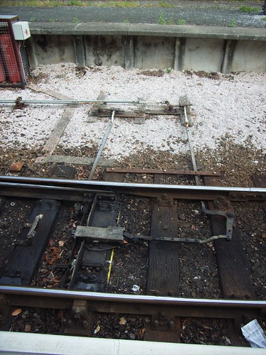
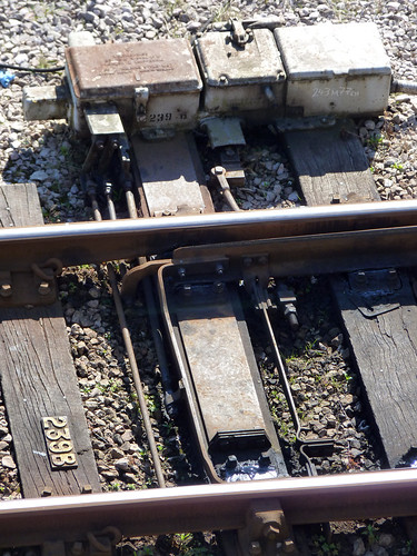
First thing to consider is the prototype. In the first half of the sixties a mix of flat bottom and bullhead rail in 60' lengths was in use on BR(S). On the main line at Crewkerne flat bottom rail was in use but anywhere along the main line you could find a mix of both. Sidings were still in bullhead and turnouts remained in bullhead due to the high cost of replacement. At this time wooden sleepers were the norm.

For model track my first decision is to use r-t-r turnouts, as I see no benefit in making these for 00 gauge when the track gauge is so unprototypical. Disregarding 'toy' track the r-t-r- options are either Tillig or Peco. Neither products are accurate to UK prototype. Tillig being for overseas networks and Peco - well the sleeper spacing and size is wrong, the chairs unrealistic, has cosmetic mechanics around the tie bar that bear no resemblance to the prototype and it's flat bottom! This just goes to show that compromise is necessary, which for the 00 gauge modeller (who is already living with an inaccurate track gauge) should not be an issue.

I bought myself a Peco code 75 elctrofrog turnout for trials. Sit this alongside a code 100 and the difference is (remarkably) not that significant. It's mainly the wide flat bottom of code 100 that makes it look too bulky when viewed from above. This is where code 75 has an extra advantage since it's narrower flat bottom is not far off the desired bullhead in appearance.

The Peco code 75 has much finer and tidier appearance than code 100 around the frog (i.e. the V) because there are no breaks in the rail, which brings us to the major technical difference. The frog and switch blades are electrified throughout. This means the locomotive has consistent power feed throughout its journey through the turnout and as a consequence trouble free running at slow speeds. The downside is course-scale metal wheels may cause momentary shorting through the switch blade. For command and control systems this event would result in fail safe cut out of power and possibly longer term damage. Peco have made provision in the design for the User to rewire the turnout and circumnavigate the shorting issue, but this also requires an electrical switch that is mechanically connected to the switch blade movement. I'd like to avoid that if possible so my next step is to set up a live test and run all my stock through.

By the way, point operation is currently by means of a finger rather than remote control and this shall probably prevail.

To Part 2

Sunday 15 May 2011

ExpoEM 2011 - A pilgrimage

It was possible to miss a model layout at this years show (except Mostyn - massive at 24' x 30' with 34 fiddle yard tracks!) because most of the stands were either trade sales or EM gauge demonstrations. This is to be expected due to the specialism of EM gauge. But, tucked away in a centre isle was the layout I came to see - Leighton Buzzard (Linslade) by Peter Denny (deceased). Denny's modelling was an inspiration to many modellers of a certain age and greying hair, like myself. So, it was a privilege to see one of his working layouts in its entirety. This particular layout design dates from the early 1970s, although much of the rolling stock and buildings are older - The station building dating from 1951, for example! Now, you need to view this layout in the context of its great age and remember that nearly everything was scratch built by Denny. 

The build and detail of his models stand up extremely well alongside current modelling technology and methods. If you have to point a finger at anything then you might suggest his method of creating model vegetation (lichen trees and dyed sawdust grass?) could do with an overhaul. But, I doubt that will happen if the objective of the new owner is to preserve the model in its historical context. Anyone who has read Denny will know that he was an innovative modeller. Who can remember his wooden 'piano key' style point lever frame. Well there it was - still in use with the wood now totally discoloured from years of human finger activity, like a well worn book. The display was supported by a lecture given by The 'Grandborough Signalman' who introduced some aspects of Denny's modelling masterpiece and life interspersed with a few anecdotes. Even Denny's two sons were on hand to fill in the knowledge gaps. I do hope the layout will be exhibited again. It needs to be seen by modellers who should pay homage to the work of the great man upstairs who inspired their own efforts.


Sunday 8 May 2011

Screw Link Couplings


In a previous posting I noted that my 4mm scale Merchant Navy Pacific loco lacked a chain link coupling and vacuum pipe. That is now corrected and this posting is about how the chain link was made. Forgive the crudity of the item in the photo. It is very, very small in reality and hardly visible when fitted to the loco. Why bother at all might you ask - well making this appeals to my creative nature and it makes my Hornby loco look even more authentic than it already is. 

The method of construction was based on the 'How to' at Southern E-Group. I had to modify the screw link part of the build because the Merchant Navy coupling has an extra half chain link. If you read the Southern E-Group method together with this photo then I think it should be clear what I did. Note that the extra half link is on the left of the screw and a tight loop is used at the other end to hold a full size chain link. 

The missing right hand vacuum pipe was lifted from my spares box. With a bit of judicious cutting this particular pipe both looked like the Merchant navy pipe and facilitated holding the chain end for storage.

On the prototype there appears to be a hook or something down there to hold the chain. Furthermore, care was needed to clear a boss that sticks out on the front of the bogie chassis. I could have filed it down but fortunately the vacuum pipe is forward enough to hold the chain out of the way. Perhaps I should say that the coupling is a cosmetic addition, not functional. I painted the coupling in-situ, otherwise the paint may have clogged up the linkage making it difficult to manoeuvre into position. The Hornby supplied hook already had provision to hold a chain, which makes me wonder if the manufacturer fits one and it was missing from my purchase?

Friday 8 April 2011

ACE Reporting Number

This came about after I watched Jim Clemens 'The Withered Arm' for the fourth time. The narrator (his son Michael) made the briefest of comments that the ACE loco in view was showing the number 6, the reporting number allocated to the 'down' ACE. His comment from earlier viewings did not register with me so armed with this new information, well new to me, I browsed my railway books that I have scoured many times before and there in the ACE photos was the number 6, which had also previously escaped me. On another photo I discovered the 'up' ACE used the reporting number 7.

Now, I knew about reporting numbers, (They were read by signallers in particular to identify a specific train service and route the train correctly, mostly used on busy or congested routes) but I had not considered their use on the ACE, which with its massive name board could not be easily mistaken.

The number for the model was printed on a sticky label using 'Arial Narrow' font size 8, a close approximation to the prototype.

Saturday 12 March 2011

BNHMS expo review

Just returned from the Basingstoke & Nth. Hants model railway show. The exhibition is spread over 5 large school rooms interconnected by a rabbit warren of corridors. I completely missed one of the rooms at last years show because of this, despite having a floor plan to hand. This year I made sure I found everything.

Trade stands were in abundance, especially RTR stock and kits. It only lacks the more specialist traders seen at shows like expoEM. I'm in the process of changing my Lima Mk1 coaches for the finely detailed Bachmann versions and managed to pick up a new MK1 SO in BR Green at a bargain price. Especially pleased about this as Bachmann themselves are currently out of stock!

As for the model railway exhibits there was a wide range of gauges, countries and historical periods on show. As a southern fan and partial to finely detailed landscapes the layout I most wanted to see was Rowlands Castle (pictured) and it did not disappoint. Wartime Britain with military activities much in evidence. Finely detailed landscaping with military models including soldiers in various poses undertaking military manoeuvres.

Very few layouts were well lit and styled for display. Most were open with backscenes not much in evidence. One that stood out for public display was the EM layout 'Cornwallis Yard', viewed through its black proscenium arch with intense stage lighting. At each end the railway tracks exit stage with an unlandscaped, wide, circular sweep meeting at the rear open fiddle yard. To some extent they unfortunately dwarf the scenic model - more scope for landscaping there I feel.

The most surprising layout was the gauge 3 'Warton Road'. Not often do we see such large scale (half inch to the foot) for a table top layout!

Sunday 6 March 2011

Take a Length of Copper Wire

The platform seat on the right in photo. is a fair representation of an LSWR 9' bench commonly seen on stations throughout the Southern Region of BR in the 1960s. The 4mm scale model was fabricated from thin copper wire hammered flat, each piece carefully formed with thin nosed pliers and soldered. Holding it in a vice as each piece was added acted as a heat sink so that previously soldered parts were less inclined to desolder and fall off. 5 slats for the seat and three for the backrest with the topmost being deeper than the others. I feel that the front to back depth of the seat should be another mm. or two deeper. 

The seat in front is an oddity. It can be seen in photos of Crewkerne Station from the 1950s to - well I photographed Crewkerne in the 1970s and it was still there! 5 slats for the base and 1 for the backrest. No arm rests and a less elaborate sub frame.

Tuesday 25 January 2011

R226 Gangways

Recently I won a second Triang R226 Maunsell GBL (Gangwayed Bogie Luggage) van on Ebay for my 1960s early morning Waterloo-Exeter newspaper train*. Now that I have two I could fabricate some gangway corridor connections. 

The method was described in my earlier posting for Bachmann bulleid coaches but for the GBL the roof is semi-circular instead of flat(ish). I was unsure if this apparent more rigid arrangement would cause interference on curves but as you can see here the two halves slide over each other nicely. The distance between the vans is unprototypical but I was not inclined to modify these vintage models. Having said that though I did fit flush windows, as described earlier. Altogether pleasing additions to these models.

* Whilst the GBL saw service throughout the 1960s I have since read that the South West Division newspaper trains used Bogie Van B rather than GBL. After 1962 GUVs were used. Also, at some time in the 1960s GBLs had their gangways removed.

Related Posts Plugin for WordPress, Blogger...