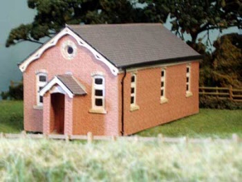
Congregational Chapel
Plastic Flora and Real Moss
Just a sample of what's available.


| Item Link | Brand |
|---|---|
| 3MT class locomotive | Tri-Ang Hornby |
| GWR Mink D | Peco Parkside Kit |
| Esso Tanker | Airfix Kit |
| 24.5T Mineral Wagon | ? |
| GWR High Bar 7-Plank open wagon | Cooper Craft Kit |
| McCain Beefeater Chips van | Lima |
| Blue Circle Cement Wagon | Airfix Kit |
Another broken wagon stored away for decades. This one was so far gone that it was destined for the bin except, I enjoyed my previous wagon repairs so much that I decided to give it a second chance.
It is the Parkside PC38 Mink D general merchandise van kit. A GWR design that saw service until during the second world war. This is before the period that I model. Incidentally 'Mink' is a shorthand code devised by GWR to define a range of goods vehicles.
Further research revealed that 10 were converted for Departmental use (9 in 1947 and 1 in 1955). These vans were in use on BR(W) throughout the 1960s (my modelled period). They carried the 'Enpart' sign and conveyed locomotive parts. The conversion resulted in different style end panels and the underframe is different to the Parkside model. I have not modified my model in this respect.
I model the BR Southern Region main line in the west country not Western Region. The Western took over that part of the Southern Region in 1963, giving me some licence for it to run on my layout, although I doubt it ever did in reality.
 Nearly all detail was missing from the model underframe. Most notably the axle boxes and springs. These I had previously cut out for use on a scratch build wagon. That wagon was subsequently retired so, with careful manipulation the superglue fixing the four axle boxes/springs in place was severed and the parts reapplied to the Mink.
Wheels, couplings, vacuum cylinder, vacuum pipes and two buffers came from my stock.
The other two buffers I could have 3D resin printed but it is such a faff to set up and clean up resin printing it is not worth the effort for such a small job. Instead, the shanks were fabricated from proprietary kit sprues with 3D FDM printed discs applied.

 Difficult to confirm the brand of this assembled kit. From remnants of the coupling supports it looks like Cooper Craft but I could not find an example on the web. It is not Parkside because that one has a little more detail.
It is a twenty four and a half ton mineral wagon.
Any way, it was another broken model stored away for decades brought out for repair.
One tie bar was severed mid way along its length and half of the other one was missing. Couplings and three buffer discs also missing.
I noticed in prototype photos that door stops, either one per door or two per door were fitted. None were on this model and no evidence of provision for them either.
Out with the 3D printer again to make the missing parts, including door stops. The couplings are proprietary. I did not have sufficient NEM sockets in stock so these were designed and printed too but they are somewhat bulkier than proprietary parts.
The wagon was repainted, decals applied (designed and printed on sticky back paper) and a weight fixed inside.

 This time it is the Cooper Craft GWR High Bar 7-Plank open wagon (not currently marketed).
It had been stored away for decades due to damage. One set of wheels was missing. The coupling 'D' bar was missing from one end and the hook from the other. One brake lever and the brakes & hangers from one side were also missing.
Fortunately, I found the wheels and compatible brakes & hangers in my spares box but, one pin point of the wheel axle was missing. To repair this I filed the end of 1 mm diameter steel wire to a point, drilled a hole in the axle end and glued it in place.


Repairing and creating the missing parts for broken rolling stock (that has been in storage for decades) is proving to be surprisingly enjoyable.
This one is the assembled Airfix Esso Tanker kit, dating from the 1960s. Available today from the Dapol Kitmaster range.
The tank and ladders had become detached and it was missing the wheels, one Esso logo, two brake blocks, a vacuum pipe and couplings.

Lead weights were cut to fit unobtrusively between chassis beams and glued in place.
There are two more wagons in the pipeline.
 No, it's not the head code, nor the missing coach. It is the chassis, not that you can see the detail in these poor photos.
The top photo is Battle of Britain 'Biggin Hill' comprising an Airfix kit body on a Kemilway nickel silver etched chassis kit. Both dating from about 1976.
The Kemilway chassis (no longer marketed) makes up into a highly detailed chassis with compensation that requires some skill to assembly. Provision is made for the wheels & axles, gear and motor that had to be purchased separately.

I am sure my model once ran satisfactorily but after nearly 50 years the chassis is showing its age with parts becoming detached and prone to short circuits. It became a poor runner causing much frustration.
I intended to break and bin it but looking at it again the bodywork is decent so, why not keep it as a static model? The second photo shows the result. Not with a Kemilway chassis but with the original Airfix chassis, the parts for which I had kept in storage for the past 50 years! Except, half the front bogie was missing so I recovered and fitted the Kemilway bogie, only to later find the missing Airfix part in another place.
Why bother replacing the chassis you may well ask. Well, my reasoning is this:
1. The Kemilway has not aged well and every time I look at it I may be tempted to repair it to run again. I fear it would need a complete strip down, clean up and reassemble to give it justice which, I am not in the mind to do.
2. There in storage is all the parts to make the Airfix chassis. Whilst not as detailed as the Kemilway it should be easier to build. How wrong could I be.
The Airfix chassis was more weird and complicated than I thought. For some obscure reason the centre driving wheels do not have flanges, rather like early Tri-ang locomotives. I could not stand that so designed 3D FDM 'rings' that were glued in place - much better. Now, the instructions assume you will assemble it so that the wheels rotate and cranks operate. This I failed to achieve due to glue leaching to where it should not be. It truly is a static model now!

Now I'll strip down the Kemilway chassis to recover usable parts.
BTW, I have another example of this locomotive class that is a working model so, this conversion is no great loss to my fleet.

The replacement bridge is now in place. It has integrated handrails and whilst these are fixed to every bridge upright and diagonal support to keep it straight there is still a bit of handrail droop between some fixing points.
Whist the Nova3D Mecha water washable resin makes for a more robust model than the Anycubic water washable resin it is just as vulnerable to warping. Hence droopy handrail.
I decided to fit the track to the bridge deck and ballast it before installing the bridge. I thought I had it lined up to the embankment track but at one end the rails were offset by only1mm, enough to derail trains.

 |
| Featuring BR1 Sleeper Chairs |


It looked decent with finely detailed bodywork and pinpoint axles. Even the inside (which is never normally seen) had detailed floor planking. However, some aspects of its design clearly showed that it was meant for play by young children rather than an accurate model of the prototype for a model railway.
The giveaways are the McCain logo (never used on real wagons), blocky buffers, roof clips that are meant to be ventilators but do not have the slope of the prototype, one piece body and chassis moulding, missing faux coupling hook, no vacuum pipes nor vacuum cylinder, no tie-bar between axle boxes, brake blocks that don't line up with the wheels and it is feather light (not weighted).
Despite these shortcomings the body detail and pinpoint axles encouraged me to turn it into a more prototypical wagon for my layout. I decided to have a look at prototype wagons to see how closely it matched. On Paul Bartlett's website I came across identical bodywork for vans designed to Diagram 1/208!
I then researched to find out more about this 'toy' and came across Lima model 305687W. But whilst having identical body style and logo it has a black chassis sporting prototypical buffer stops, and naïve, faux coupling hooks. Clearly not the same model. I found other examples of 'my' model on Ebay but nowhere could I find its history. I am guessing it came from a 'play' train set. I would like to know how it was marketed by Lima so, if you know please leave a comment.

The rectangular piece is the sloping ventilator that will be glued to the flat ventilator/roof clip. Once the roof is fitted and sloping ventilator glued in place then it will (sadly) not be possible to remove the roof from the wagon.
The yellow wagon in this photo has had the logo scratched away, the blocky buffers cut off, the 'D' coupling removed, missing tie bars installed (plasticard) and a steel weight fixed inside.

Managing Nova3D Washable Mecha Resin
This stuff has a mind of its own.
 |
| Lattice and handrails warped. The whole part also twisted. |
 |
| After a few hours curing it regains its desired shape. |
More experiences using Nova3D Washable Mecha Resin.
I do like the fact that resin particles washed off settle at the bottom of the water tank rather than remaining suspended in the water.
I do not like the excessive warping that occurs in thin plate sections, which is what this bridge is mostly composed of. But, the situation seems to be recoverable.

What I had to do was carefully tie down components where areas have warped and then cure on a shelf in sunlight. Once fully cured the parts become hard with some flexibility that resists breakage.


Three layouts sparked my interest.
Tellindalloch in Autumn (00)

This reminded me of my own Swanage loco yard model as it is about the same size, set in a black framed box and is an autumnal scene. There are issues with mine though in so far as the box has warped and operating potential is limited, since train movements focus on the single track shed and turntable. Tellindalloch inspires me to revisit mine to see if improvement can be made.
Market Bosworth (P4)

Set in the early 1900's this layout is based on a real place. It is not a period that is often modelled. The locomotives, rolling stock and road vehicles spark interest due to their 'old world' character.
Of course, being P4 the modelling is to a very high standard. The building interiors even have lighting and finely detailed furniture.
Old Elm Park (0)

There is a multitude of BR period locomotives on display. I thought they were all RTR manufacture and totted up the potential value to be around £20,000. I subsequently read that the owner is a locomotive builder so, if he had built the lot then a skilled modeller indeed.
This layout was my personal Best in Show.
 This is the distant signal at the west end of my Battledown Flyover Model Railway. The signal is made from a Ratio LNER upper quadrant signal pack UQ/80 with a customised platform. The lattice pole style and upper quadrant signal arm of the LNER signal is reasonably close in style to a Southern signal.
On the other side of the embankment is the Basingstoke to Salisbury main line and two storage sidings. When needing access to that area my arm passes over the signal. (you know what is coming).
Unbeknown to me my woolly cardigan sleeve caught and locked onto the finial and signal arm. It was carried across the room where it dropped off onto the floor, closely followed by my foot which crushed it beyond repair!


From 1983 and recently published on YouTube. This grainy video starts off with a visit to a Great Central Heritage Railway. Stick with it because most of the video is Peter Deny explaining his modelling motivation, philosophy and techniques, interspersed with images of his model railways.